Question 11.5: A steel column is constructed from a W 10 × 60 wide-flange s......
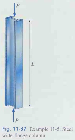
A steel column is constructed from a W 10 × 60 wide-flange section (Fig. 11-37). Assume that the column has pin supports and may buckle in any direction. Also, assume that the steel has modulus of elasticity E = 29,000 ksi and yield stress σ_y = 36 ksi. (a) If the length of the column is L = 20 ft. what is the allowable axial load? (b) If the column is subjected to an axial load P = 200 k, what is the maximum permissible length?
Learn more on how do we answer questions.
We will use the AISC formulas (Eqs. 11-79 through 11-82) when analyzing this column. Since the column has pin supports, the effective-length factor K = 1. Also, since the column will buckle about the weak axis of bending. we will use the smaller radius of gyration:
n_1=\frac{5}{3}+\frac{3\left(\frac{KL}{r}\right)}{8\left(\frac{KL}{r}\right)_c}\ -\ \frac{\left(\frac{KL}{r}\right)^3}{8\left(\frac{KL}{r}\right)_c^3}\quad \quad \frac{KL}{r}≤\left(\frac{KL}{r}\right)_c (11-79)
\frac{σ_{allow}}{σ_y}=\frac{\left(\frac{KL}{r}\right)^2_c}{2n_2\left(\frac{KL}{r}\right)^2}\quad \quad \frac{KL}{r}≤\left(\frac{KL}{r}\right)_c (11-82)
r = 2.57 in.
as obtained from Table E-1, Appendix E. The critical slenderness ratio (Eq. 11-76) is
\left(\frac{KL}{r}\right)_c=\sqrt{\frac{2π^2E}{σ_y}}=\sqrt{\frac{2π^2(29,000\ ksi)}{36\ ksi}} = 126.1 (a)
(a) Allowable axial load. If the length L = 20 ft. the slenderness ratio of the column is
\frac{L}{r}=\frac{(20\ ft)(12\ in./ft)}{2.57\ in.} = 93.4
which is less than the critical ratio (Eq. a). Therefore, we will use Eqs. (11-79) and (11-81) to obtain the factor of safety and allowable stress, respectively:
n_1=\frac{5}{3}+\frac{3\left(\frac{KL}{r}\right)}{8\left(\frac{KL}{r}\right)_c}\ -\ \frac{\left(\frac{KL}{r}\right)^3}{8\left(\frac{KL}{r}\right)_c^3}=\frac{5}{3}+\frac{3(93.4)}{8(126.1)}\ -\ \frac{(93.4)^3}{8(126.1)^3} = 1.89
\frac{σ_{allow}}{σ_y}=\frac{1}{n_1}\left[1\ -\ \frac{\left(\frac{KL}{r}\right)^2}{2\left(\frac{KL}{r}\right)^2_c}\right]\quad \quad \frac{KL}{r}≤\left(\frac{KL}{r}\right)_c (11-81)
\frac{σ_{allow}}{σ_y}=\frac{1}{n_1}\left[1\ -\ \frac{\left(\frac{KL}{r}\right)^2}{2\left(\frac{KL}{r}\right)^2_c}\right]=\frac{1}{1.89}\left[1\ -\ \frac{(93.4)^2}{2(126.1)^2}\right] = 0.384
σ_{allow}=0.384σ_y = 0.384(36 ksi) = 13.8 ksi
Since the cross-sectional area of the column is A = 17.6 in.² (from Table
E-1), the allowable axial load is
P_{allow}=σ_{allow}A= = (13.8 ksi)(17.6 in.²) = 243 k
(h) Maximum permissible length. To determine the maximum length when die axial lond P = 200k, we begin with an estimated value of length and then use a trial-and-error procedure. Note that when the load P = 200 k. the maximum length is greater than 20 ft (because a length of 20 ft corresponds to an axial load of 243 k). Therefore, as a trial value. we will assume L = 25 ft. The corresponding slenderness ratio is
\frac{L}{r}=\frac{(25\ ft)(12\ in./ft)}{2.57\ in.} = 116.7
which is less than the critical ratio. Therefore, we again use Eqs. (11-79) and (11-81) to obtain the factor of safety and allowable stress:
n_1=\frac{5}{3}+\frac{3\left(\frac{KL}{r}\right)}{8\left(\frac{KL}{r}\right)_c}\ -\ \frac{\left(\frac{KL}{r}\right)^3}{8\left(\frac{KL}{r}\right)^3_c}=\frac{5}{3}+\frac{3(116.7)}{8(126.1)}\ -\ \frac{(116.7)^3}{8(126.1)^3} = 1.915
\frac{σ_{allow}}{σ_y}=\frac{1}{n_1}\left[1\ -\ \frac{\left(\frac{KL}{r}\right)^2}{2\left(\frac{KL}{r}\right)^2_c}\right]=\frac{1}{1.915}\left[1\ -\ \frac{(116.7)^2}{2(126.1)^2}\right] = 0.299
σ_{allow}=0.299σ_y = 0.299(36 ksi) = 10.8 ksi
Thus, the allowable axial load corresponding to a length L = 25 ft is
P_{allow}=σ_{allow}A=(10.8\ ksi)(17.6\ in.^2) = 190 k
which is less than the given load of 200 k. Therefore, the permissible length is less than 25 ft.
Performing similar calculations for L = 24.0 ft and L = 24.5 ft, we obtain the following results:
L = 24.0 ft P_{allow} = 201 k
L = 24.5 ft P_{allow} = 194 k
L = 25.0 ft P_{allow} = 190 k
Interpolating between these results, we see that load of 200 k corresponds to a length of 24.1 ft. Thus, the maximum permissible length of the column is
L_{max} = 25.0 ft