Question 20.3: Figure P.20.3 shows the cross-section of a single-cell, thin......
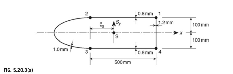
Figure P.20.3 shows the cross-section of a single-cell, thin-walled beam with a horizontal axis of symmetry. The direct stresses are carried by the booms B1 to B4, while the walls are effective only in carrying shear stresses. Assuming that the basic theory of bending is applicable, calculate the position of the shear center S. The shear modulus G is the same for all walls:
Cell area = 135, 000 mm²; Boom areas: B1=B4=450mm2,B2=B3=550mm2
Wall 12, 34 23 41 Length (mm) 500 580 200 Thickness (mm) 0.8 1.0 1.2 Answer: 197.2 mm to the right of the vertical through booms 2 and 3

Learn more on how do we answer questions.
The shear center, S, lies on the horizontal axis of symmetry, the x axis. Therefore apply an arbitrary shear load, Sy, through S (Fig. S.20.3(a)). The internal shear flow distribution is given by Eq. (20.11), which, since Ixy=0,Sx=0,andtD=0, simplifies to
qs=−(IxxIyy−Ixy2SxIxx−SyIxy)(∫0stDxds+r=1∑nBrxr)−(IxxIyy−Ixy2SyIyy−SxIxy)(∫0stDJds+r=1∑nBryr)+qs,0 (20.11)
qs=−IxxSyr=1∑nBryr+qs,0 (i)
in which
Ixx=2×450×1002+2×550×1002=20×106mm4Equation (i) then becomes
qs=−0.5×10⁻⁷Sy∑r=1nBryr+qs,0 (ii)
The first term on the right-hand side of Eq. (ii) is the qb distribution (see Eq. (17.16)). To determine qb, ‘cut’ the section in the wall 23. Then
qs=qb+qs,0 (17.16)
The value of shear flow at the ‘cut’ is obtained using Eq. (17.28), which, since G= constant, becomes
qs,0=−∮ds∮qbds (17.28)
qs,0=−∮ds/t∮(qb/t)ds (iii)
In Eq. (iii),
∮tds=1.0580+2×0.8500+1.2200=1996.7Then, from Eq. (iii) and the above qb distribution,
qs,0=−1996.7Sy(2×0.82.75×10−3×500+1.25.0×10−3×200)i.e.,
qs,0=−2.14×10⁻³SyThe complete shear flow distribution is shown in Fig. S.20.3(b).
Now taking moments about O in Fig. S.20.3(b) and using the result of Eq. (20.10),
Mq=2Aq12 (20.10)
SyξS=2×0.61×10−3Sy×500×100+2.86×10−3Sy×200×500−2.14×10−3Sy×2(13500−500×200)which gives
ξ8=197.2mm