For the two gears, A and B, in Figure 3–23, compute the relative deflection between them in the plane of the paper that is due to the forces shown in Figure 3–23 (c). These separating forces, or normal forces, are discussed in Chapters 9 and 10. It is customary to consider the loads at the gears and the reactions at the bearings to be concentrated. The shafts carrying the gears are steel and have uniform diameters as listed in the figure.

Objective: Compute the relative deflection between gears A and B in Figure 3-23.
Given: The layout and loading pattern are shown in Figure 3-23. The separating force between gears A and B is 240 \mathrm{lb}. Gear A pushes downward on gear B, and the reaction force of gear B pushes upward on gear A. Shaft 1 has a diameter of 0.75 in and a moment of inertia of 0.0155 \mathrm{in}^{4}. Shaft 2 has a diameter of 1.00 in and a moment of inertia of 0.0491 in^{4}. Both shafts are steel. Use E=30 \times 10^{6} \mathrm{psi}.
Analysis: Use the deflection formulas from Appendix 14 to compute the upward deflection of shaft 1 at gear Aand the downward deflection of shaft 2 at gear B. The sum of the two deflections is the total deflection of gear A with respect to gear B.
Case (a) from Table A14–1 applies to Shaft 1 because there is a single concentrated force acting at the midpoint of the shaft between the supporting bearings. We will call that deflection y_A.
Shaft 2 is a simply supported beam carrying two nonsymmetrical loads. No single formula from Appendix 14 matches that loading pattern. But we can use superposition to compute the deflection of the shaft at gear B by considering the two forces separately as shown in Part (d) of Figure 3–23. Case (b) from Table A14–1 is used for each load.
We first compute the deflection at B due only to the 240-lb force, calling it y_{B1}. Then we compute the deflection at B due to the 320-lb force, calling it y_{B2}. The total deflection yat B \text { is } y_{B}=y_{B 1}+y_{B 2}.
Results: The deflection of shaft 1 at gear A is
y_{A}=\frac{F_{A} L_{1}^{3}}{48 E I}=\frac{(240)(6.0)^{3}}{48\left(30 \times 10^{6}\right)(0.0155)}=0.0023 \text { in }
The deflection of shaft 2 at B due only to the 240-\mathrm{lb} force is
y_{B 1}=-\frac{F_{B} a^{2} b^{2}}{3 E I_{2} L_{2}}=-\frac{(240)(3.0)^{2}(11.0)^{2}}{3\left(30 \times 10^{6}\right)(0.0491)(14)}=-0.0042 \text { in }
The deflection of shaft 2 at B due only to the 320-\mathrm{lb} force at C is
\begin{aligned}&y_{B 2}=-\frac{F_{c} b x}{6 E I_{2} L_{2}}\left(L_{2}^{2}-b^{2}-x^{2}\right) \\&y_{B 2}=-\frac{(320)(3.0)(3.0)}{6\left(30 \times 10^{6}\right)(0.0491)(14)}\left[(14)^{2}-(3.0)^{2}-(3.0)^{2}\right] \\&y_{B 2}=-0.0041 \text { in }\end{aligned}
Then the total deflection at gear B is
y_{B}=y_{B 1}+y_{B 2}=-0.0042-0.0041=-0.0083 \text { in }
Because shaft 1 deflects upward and shaft 2 deflects downward, the total relative deflection is the sum of y_{A} and y_{B} :
y_{\text {total }}=y_{A}+y_{B}=0.0023+0.0083=0.0106 \text { in }
Comment: This deflection is very large for this application. How could the deflection be reduced?
| TABLE A14–1 Beam-Deflection Formulas for Simply Supported Beams | |
| \mathrm{y}_{B}=\mathrm{y}_{\max }=\frac{-P L^{3}}{48 E I} \quad \text { at center } Between A and B; \mathrm{y}=\frac{-P x}{48 E l}\left(3 L^{2}-4 x^{2}\right) |
 |
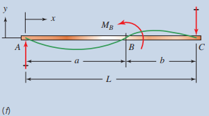
| \begin{gathered}y_{\max }=\frac{-P a b(L+b) \sqrt{3 a(L+b)}}{27 E I L} \\\text { at }x_{1}=\sqrt{a(L+b) / 3} \\y_{B}=\frac{-P a^{2} b^{2}}{3 E / L} \text { at load }\end{gathered} BetweenA and B (the longer segment): y=\frac{-P b x}{6 E / L}\left(L^{2}-b^{2}-x^{2}\right) Between B and C (the shorter segment): y=\frac{-P a v}{6 E I L}\left(L^{2}-v^{2}-a^{2}\right) At end of overhang at D : y_{D}=\frac{P a b c}{6 E I L}(L+a) |
 |
| \begin{gathered}y_{E}=y_{\max }=\frac{-P a}{24 E I}\left(3 L^{2}-4 a^{2}\right) \text {at center } \\y_{B}=y_{C}=\frac{-P a^{2}}{6 E I}(3 L-4 a) \text { at loads }\end{gathered} Between A and B : y=\frac{-P x}{6 E I}\left(3 a L-3 a^{2}-x^{2}\right) Between B and C : y=\frac{-P a}{6 E I}\left(3 L x-3 x^{2}-a^{2}\right) |
 |
| y_{B}=y_{\max }=\frac{-5 w L^{4}}{384 E l}=\frac{-5 W L^{3}}{384 E I} \text { at center } Between A and B : y=\frac{-w x}{24 E l}\left(L^{3}-2 L x^{2}+x^{3}\right) At D at end: y_{D}=\frac{w L^{3} a}{24 E I} |
 |
| Between A and B : y=\frac{-w x}{24 E I L}\left[a^{2}(2 L-a)^{2}-2 a x^{2}(2 L-a)+L x^{3}\right] Between B and C : y=\frac{-w a^{2}(L-x)}{24 E I L}\left(4 L x-2 x^{2}-a^{2}\right) |
 |
| M_{B}=\text { concentrated moment at } B Between A and B : y=\frac{-M_{B}}{6 E I}\left[\left(6 a-\frac{3 a^{2}}{L}-2 L\right) x-\frac{x^{3}}{L}\right] Between B and C : y=\frac{M_{B}}{6 E I}\left[3 a^{2}+3 x^{2}-\frac{x^{3}}{L}-\left(2 L+\frac{3 a^{2}}{L}\right) x\right] |
 |
| At C at end of overhang: y_{C}=\frac{-P a^{2}}{3 E l}(L+a) At D, maximum upward deflection: y_{D}=0.06415 \frac{P a L^{2}}{E l} |
 |
| At C at center: y=\frac{-W L-2 a)^{3}}{384 E l}\left[\frac{5}{L}(L-2 a)-\frac{24}{L}\left(\frac{a^{2}}{L-2 a}\right)\right] At A and E at ends: y=\frac{-W L-2 a)^{3} a}{24 E I L}\left[-1+6\left(\frac{a}{L-2 a}\right)^{2}+3\left(\frac{a}{L-2 a}\right)^{3}\right] |
 |
| At C at center: y=\frac{P L^{2} a}{8 E I} At A and E at ends at loads: y=\frac{-P a^{2}}{3 E I}\left(a+\frac{3}{2} L\right) |
 |
| At B : y=0.03208 \frac{w a^{2} L^{2}}{E l} At D at end: y=\frac{-w a^{3}}{24 E l}(4 L+3 a) |
 |
| TABLE A14–2 Beam-Deflection Formulas for Cantilevers | |
| At B at end: y_{B}=y_{\max }=\frac{-P L^{3}}{3 E I} Between A and B: y=\frac{-P x^{2}}{6 E I}(3 L-x) |
 |
| At B at load: y_{B}=\frac{-P a^{3}}{3 E I} At C at end: y_{C}=y_{\max }=\frac{-P a^{2}}{6 E I}(3 L-a) Between A and B : y=\frac{-P x^{2}}{6 E I}(3 a-x) Between B and C : y=\frac{-P a^{2}}{6 E I}(3 x-a) |
 |
| W=\text { total load }=w L At B at end: y_{B}=y_{\max }=\frac{-W L^{3}}{8 E I} Between A and B : y=\frac{-W x^{2}}{24 E I L}\left[2 L^{2}+(2 L-x)^{2}\right] |
 |
| M_{B}= concentrated moment at end At B at end: y_{B}=y_{\max }=\frac{-M_{B} L^{2}}{2 E I} Between A and B : y=\frac{-M_{B} x^{2}}{2 E I} |
 |
| TABLE A14–3 Beam Diagrams and Beam-Deflection Formulas for Statically Indeterminate Beams | |
| Deflections At B at load: y_{B}=\frac{-7}{768} \frac{P L^{3}}{E I} y_{\max } is at v=0.447 L at D : y_{D}=y_{\max }=\frac{-P L^{3}}{107 E I} Between A and B : y=\frac{-P x^{2}}{96 E I}(9 L-11 x) Between B and C : y=\frac{-P v}{96 E I}\left(3 L^{2}-5 v^{2}\right) |
 |
| Reactions \begin{aligned}&R_{A}=\frac{P b}{2 L^{3}}\left(3 L^{2}-b^{2}\right) \\&R_{C}=\frac{Pa^{2}}{2 L^{3}}(b+2 L)\end{aligned} Moments \begin{aligned}&M_{A}=\frac{-P a b}{2 L^{2}}(b+L) \\&M_{B}=\frac{P a^{2} b}{2 L^{3}}(b+2 L)\end{aligned} Deflections At B at load: y_{B}=\frac{-P a^{3} b^{2}}{12 E I L^{3}}(3 L+b) Between A and B : \begin{aligned}y &=\frac{-P x^{2} b}{12 E I L^{3}}\left(3 C_{1}-C_{2} x\right) \\C_{1}&=a L(L+b) ; C_{2}=(L+a)(L+b)+a L\end{aligned} Between B and C : y=\frac{-P a^{2} v}{12 E I L^{3}}\left[3 L^{2} b-v^{2}(3 L-a)\right] |
 |
| Reactions \begin{aligned}&R_{A}=\frac{5}{8} W \\&R_{B}=\frac{3}{8} W\end{aligned} Moments \begin{aligned}&M_{A}=-0.125 W L \\&M_{E}=0.0703 W L\end{aligned} Deflections. At C at x=0.579 L: y_{C}=y_{\max }=\frac{-W^{3}}{185 E I} At D at center: y_{D}=\frac{-W L^{3}}{192 E I} Between A and B : y=\frac{-W x^{2}(L-x)}{48 E I L}(3 L-2 x) |
 |
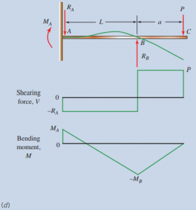
| Reactions \begin{aligned}&R_{A}=\frac{-3 P a}{2 L} \\&R_{B}=P\left(1+\frac{3 a}{2 L}\right)\end{aligned} Moments \begin{aligned}&M_{A}=\frac{P a}{2} \\&M_{B}=-P a\end{aligned} Deflection At C at end: y_{C}=\frac{-P L^{3}}{E I}\left(\frac{a^{2}}{4 L^{2}}+\frac{a^{3}}{3 L^{3}}\right) |
 |
| Moments M_{B}=P L / 8 ; M_{A}=M_{C}=-P L / 8 Deflections At B at center: y_{B}=y_{\max }=\frac{-P L^{3}}{192 E I} Between A and B : y=\frac{-P x^{2}}{48 E I}(3 L-4 x) |
 |
| Reactions. \begin{aligned}&R_{A}=\frac{P b^{2}}{L^{3}}(3 a+b) \\&R_{C}=\frac{P a^{2}}{L^{3}}(3b+a)\end{aligned} Moments \begin{aligned}&M_{A}=\frac{-P a b^{2}}{L^{2}} \\&M_{B}=\frac{2 P a^{2} b^{2}}{L^{3}} \\&M_{C}=\frac{-P a^{2} b}{L^{2}}\end{aligned} Deflections At B at load: y_{B}=\frac{-P a^{3} b^{3}}{3 E I L^{3}} At D at x_{1}=\frac{2 a L}{3 a+b} y_{D}=y_{\max }=\frac{-2 P a^{3} b^{2}}{3 EI(3 a+b)^{2}} Between A and B (longer segment): y=\frac{-P x^{2} b^{2}}{6 E I L^{3}}[2 a(L-x)+L(a-x)] Between B and C (shorter segment): y=\frac{-P v^{2} a^{2}}{6 E I L^{3}}[2 b(L-v)+L(b-v)] |
 |
| Moments \begin{aligned}&M_{A}=M_{C}=\frac{-W L}{12} \\&M_{B}=\frac{W L}{24}\end{aligned} Deflections At B at center: y_{B}=y_{\max }=\frac{-W L^{3}}{384 E I} Between A and C : y=\frac{-w x^{2}}{24 E I}(L-x)^{2} |
 |
| Reactions \begin{array}{r}R_{A}=R_{C}=\frac{3 w L}{8} \\R_{B}=1.25 w L\end{array} Shearing forces \begin{aligned}&V_{A}=V_{C}=R_{A}=R_{C}=\frac{3 w L}{8} \\&V_{B}=\frac{5 w L}{8}\end{aligned} Moments \begin{gathered}M_{D}=M_{E}=0.0703 w L^{2} \\M_{B}=-0.125 w L^{2}\end{gathered} Deflections At x_{1}=0.4215 L from A or C : y_{\max }=\frac{-w L^{4}}{185 E I} Between A and B : y=\frac{-w}{48 E I}\left(L^{3} x-3 L x^{3}+2 x^{4}\right) |
 |
| Reactions \begin{aligned}&R_{A}=R_{D}=0.4 w L \\&R_{B}=R_{C}=1.10 w L\end{aligned} Mornents \begin{aligned}&M_{E}=M_{F}=0.08 w L^{2} \\&M_{B}=M_{C}=-0.10 w L^{2}=M_{\max } \\&M_{G}=0.025 w L^{2}\end{aligned} |
 |
| Reactions \begin{aligned}&R_{A}=R_{E}=0.393 w L \\&R_{B}=R_{D}=1.143 w L \\&R_{C}=0.928 w L\end{aligned} Shearing forces \begin{aligned}V_{A} &=+0.393 \mathrm{wL} \\-V_{B} &=-0.607 \mathrm{wL} \\+V_{B}&=+0.536 \mathrm{wL} \\-V_{C} &=-0.464 \mathrm{wL} \\+V_{C} &=+0.464 \mathrm{wL} \\-V_{D}&=-0.536 \mathrm{wL} \\+V_{D} &=+0.607 \mathrm{wL} \\-V_{E} &=-0.393 \mathrm{wL}\end{aligned} Moments \begin{aligned}&M_{B}=M_{D}=-0.1071 w L^{2}=M_{\max } \\&M_{F}=M_{l}=0.0772 w L^{2} \\&M_{C}=-0.0714 w L^{2} \\&M_{G}=M_{H}=0.0364 w L^{2}\end{aligned} |
 |