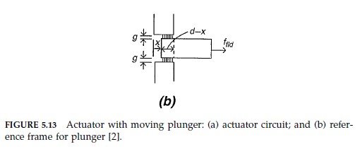
Question 5.8.1: Consider the magnetic actuator circuit shown in Fig. 5.13a. ...
Consider the magnetic actuator circuit shown in Fig. 5.13a. Assume that the magnetic circuit operates in a linear region of its B-H curve with μ >> μ_{o}, and that there is no flux leakage. Determine the force on the plunger [2].

Learn more on how we answer questions.
We determine an analytical expression for the force on the plunger using both energy and coenergy approaches. Choose a convention in which a positive f_{fld} is in the direction of increasing displacement x as shown.
Energy: In the energy approach, Λ and x are the independent variables and the energy is determined using Eq. (5.129),
Eq. (5.129):W_{fld}= \left\{\begin{matrix} \frac{Λi(Λ,x)}{2}=\frac{Λ^{2}}{2L(x)} \text{(linear motion)} \\ \frac{Λi(Λ,θ)}{2}=\frac{Λ^{2}}{2L(θ)} \text{(rotational motion)}\end{matrix} \right.
W_{fld} = \frac{Λ^{2}}{2L(x)} (5.149)
We need to determine the inductance L(x). We use the inductance relation (3.75).
L = \frac{1}{i^{2}} \int_{V} B · H dv. (5.150)
As μ >> μ_{0}, the core and plunger have a high permeability and the H-field in these elements is negligible. Therefore, Eq. (5.150) reduces to an integration over the gap regions,
L = \frac{2}{i^{2}} \int_{V_{g}} B · H dv, (5.151)
where V_{g} = wg(d – x) is the volume of the gap. Factor 2 in Eq. (5.151) takes into account the identical integrations over the gap regions above and below the plunger. To evaluate Eq. (5.151) we need to know the fields B_{g} and H_{g} in the gap. To this end, apply Eq. (3.141) to a path around the circuit through the plunger and obtain
Eq. (3.141): \oint_{C} H· dl = \sum\limits_{i=1}^{m} H_{i} l_{i} = I_{tot}
2H_{g} g = ni,
which gives
H_{g} = \frac{ni}{2g}.
Further, B_{g} = μ_{0} H_{g}. Substitute B_{g} and H_{g} into Eq. (5.151) and obtain
L(x) = \frac{μ_{0}n^{2}w}{2g} (d – x). (5.152)
Then, substitute this into Eq. (5.149), which gives
W_{fld}(Λ,x) = \frac{gΛ^{2}}{μ_{0}n^{2}w (d – x)} (5.153)
Finally, obtain the force using Eq. (5.127),
Eq. (5.127): f_{fld} = -\frac{∂W_{fld}(Λ,x)}{∂x} (linear motion)
T_{fld} = -\frac{∂W_{fld}(Λ,θ)}{∂θ} (rotational motion)
f_{fld} = -\frac{∂W_{fld}(Λ,x)}{∂x}
= -\frac{gΛ^{2}}{μ_{0}n^{2}w (d – x)^{2}} (5.154)
As 0 ≤ x < d and Λ^{2} > 0, the force is negative, which means that it acts to pull the plunger towards the core (in the direction of decreasing x). Formula (5.154) would be more useful if we had an explicit expression for Λ. For an n-turn coil we have Λ = nΦ where Φ is the flux through each turn of the coil. As there is no flux leakage, Φ = Φ_{g} = B_{g} A_{g} where A_{g} = w(d – x). Therefore
Φ = \frac{μ_{0}}{2} \frac{ni}{g} w (d – x) and Λ = \frac{μ_{0}n^{2} i}{2g}w (d – x)
Coenergy: In the coenergy approach i and x are the independent variables and the coenergy is given by Eq. (5.139),
Eq. (5.139): W_{fld}^{c} = \left\{\begin{matrix} \frac{Λ(i,x)i}{2}=\frac{L(x)i^{2}}{2} \text{(linear motion)} \\ \frac{Λ(i,θ)i}{2}=\frac{L(θ)i^{2}}{2} \text{(rotational motion)}\end{matrix} \right.
W_{fld}^{c} = \frac{L(x) i^{2}}{2} (5.155)
Substitute Eq. (5.152) into Eq. (5.155) and obtain
W_{fld}^{c} = \frac{μ_{0}i^{2} n^{2}}{4g}w (d – x) (5.156)
The force follows from Eq. (5.138),
Eq. (5.138): f_{fld} = \frac{∂W_{fld}^{c}(i,x)}{∂x} (linear motion)
T_{fld} = \frac{∂W_{fld}^{c}(i,θ)}{∂θ} (rotational motion)
f_{fld}= – \frac{μ_{0}i^{2} n^{2} w}{4g} (5.157)
Notice that the force is independent of x. The two force expressions (5.154) and (5.157) are equivalent. To see this, substitute Eq. (3.78) (i.e., ΛL(x)i) into Eq. (5.154), which gives Eq. (5.157).