Question 8.6: A sign of dimensions 2.0 m × 1.2 m is supported by a hollow ...
A sign of dimensions 2.0 m × 1.2 m is supported by a hollow circular pole having outer diameter 220 mm and inner diameter 180 mm (Fig. 8-26). The sign is offset 0.5 m from the centerline of the pole and its lower edge is 6.0 m above the ground.
Determine the principal stresses and maximum shear stresses at points A and B at the base of the pole due to a wind pressure of 2.0 kPa against the sign.

Learn more on how we answer questions.
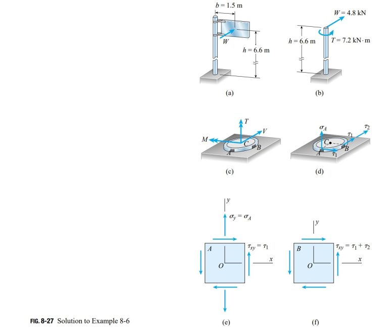
Stress resultants. The wind pressure against the sign produces a resultant force W that acts at the midpoint of the sign (Fig. 8-27a) and is equal to the pressure p times the area A over which it acts:
W = pA = (2.0 kPa)(2.0 m × 1.2 m) = 4.8 kN
The line of action of this force is at height h = 6.6 m above the ground and at distance b = 1.5 m from the centerline of the pole.
The wind force acting on the sign is statically equivalent to a lateral force W and a torque T acting on the pole (Fig. 8-27b). The torque is equal to the force W times the distance b:
T = Wb = (4.8 kN)(1.5 m) = 7.2 kN·m
The stress resultants at the base of the pole (Fig. 8-27c) consist of a bending moment M, a torque T, and a shear force V. Their magnitudes are
M = Wh = (4.8 kN)(6.6 m) = 31.68 kN·m
T = 7.2 kN·m V = W = 4.8 kN
Examination of these stress resultants shows that maximum bending stresses occur at point A and maximum shear stresses at point B. Therefore, A and B are critical points where the stresses should be determined. (Another critical point is diametrically opposite point A, as explained in the Note at the end of this example.)
Stresses at points A and B. The bending moment M produces a tensile stress \sigma_{A} at point A (Fig. 8-27d) but no stress at point B (which is located on the neutral axis). The stress \sigma_{A} is obtained from the flexure formula:
in which d_{2} is the outer diameter (220 mm) and I is the moment of inertia of the cross section. The moment of inertia is
I=\frac{\pi}{64}\left(d^{4}_{2}-d^{4}_{1}\right)=\frac{\pi}{64}\left[(220 mm)^{4}-(180 mm)^{4}\right]=63.46\times10^{-6} m^{4}in which d_{1} is the inner diameter. Therefore, the stress \sigma_{A} is
\sigma_{A}=\frac{Md_{2}}{2I}=\frac{(31.68 kN\cdot m)(220 mm)}{2(63.46\times 10^{-6} m^{4})}=54.91 MPaThe torque T produces shear stresses \tau_{1} at points A and B (Fig. 8-27d). We can calculate these stresses from the torsion formula:
\tau_{1}=\frac{T(d_{2}/2)}{I_{P}}in which I_{P} is the polar moment of inertia:
I_{P}=\frac{\pi}{32}\left(d^{4}_{2}-d^{4}_{1}\right)=2I=126.92\times10^{-6} m^{4}Thus,
\tau_{1}=\frac{Td_{2}}{2I_{P}}=\frac{(7.2 kN\cdot m)(220 mm)}{2(126.92\times 10^{-6} m^{4} )}=6.24 MPaFinally, we calculate the shear stresses at points A and B due to the shear force V. The shear stress at point A is zero, and the shear stress at point B (denoted \tau_{2} in Fig. 8-27d) is obtained from the shear formula for a circular tube (Eq. 5-44 of Section 5.9):
\tau_{\max}=\frac{VQ}{Ib}=\frac{4V}{3A}\left(\frac{r^{2}_{2}+r_{2}r_{1}+r^{2}_{1}}{r^{2}_{2}+r^{2}_{1}}\right) (5-44)
\tau_{2}=\frac{4V}{3A}=\left(\frac{r^{2}_{2}+r_{2}r_{1}+r^{2}_{1}}{}\right) ( j)
in which r_{2} and r_{1} are the outer and inner radii, respectively, and A is the cross-sectional area:
r_{2}=\frac{d_{2}}{2}=110 mm r_{1}=\frac{d_{1}}{2}=90 mm
A=\pi\left(r^{2}_{2}-r^{2}_{1}\right)=12,570 mm^{2}
Substituting numerical values into Eq. (j), we obtain
\tau_{2}=0.76 MPaThe stresses acting on the cross section at points A and B have now been calculated.
Stress elements. The next step is to show these stresses on stress elements (Figs. 8-27e and f). For both elements, the y axis is parallel to the longitudinal axis of the pole and the x axis is horizontal. At point A the stresses acting on the element are
At point B the stresses are
\sigma_{x}=\sigma_{y}=0 \tau_{xy}=\tau_{1}+\tau_{2}=6.24 MPa + 0.76 MPa = 7.00 MPaSince there are no normal stresses acting on the element, point B is in pure shear.
Now that all stresses acting on the stress elements (Figs. 8-27e and f) are known, we can use the equations given in Section 7.3 to determine the principal stresses and maximum shear stresses.
Principal stresses and maximum shear stresses at point A. The principal stresses are obtained from Eq. (7-17), which is repeated here:
\sigma_{1,2}=\frac{\sigma_{x}+\sigma_{y}}{2}\pm\sqrt{\left(\frac{\sigma_{x}-\sigma_{y}}{2}\right)^{2}+\tau^{2}_{xy}} (k)
Substituting \sigma_{x} = 0, \sigma_{y} = 54.91 MPa, and \tau_{xy} = 6.24 MPa, we get
\sigma_{1,2} = 27.5 MPa ± 28.2 MPa
or
\sigma_{1} = 55.7 MPa \sigma_{2} = -0.7 MPa
The maximum in-plane shear stresses may be obtained from Eq. (7-25):
\tau_{\max}=\sqrt{\left(\frac{\sigma_{x}-\sigma_{y}}{2}\right)^{2}+\tau^{2}_{xy}} (l)
This term was evaluated previously, so we see immediately that
\tau_{\max} = 28.2 MPa
Because the principal stresses \sigma_{1} and \sigma_{2} have opposite signs, the maximum in-plane shear stresses are larger than the maximum out-of-plane shear stresses (see Eqs. 7-28a, b, and c and the accompanying discussion). Therefore, the maximum shear stress at point A is 28.2 MPa.
(\tau_{\max})_{x_{1}}=\pm \frac{\sigma_{2}}{2} (\tau_{\max})_{y_{1}}=\pm \frac{\sigma_{1}}{2} (\tau_{\max})_{z_{1}}=\pm \frac{\sigma_{1}-\sigma_{2}}{2} (7-28a,b,c)
Principal stresses and maximum shear stresses at point B. The stresses at this point are \sigma_{x} = 0, \sigma_{y} = 0, and \tau_{xy} = 7.0 MPa. Since the element is in pure shear, the principal stresses are
\sigma_{1} = 7.0 MPa \sigma_{2} = -7.0 MPa
and the maximum in-plane shear stress is
\tau_{\max} = 7.0 MPa
The maximum out-of-plane shear stresses are half this value.
Note: If the largest stresses anywhere in the pole are needed, then we must also determine the stresses at the critical point diametrically opposite point A, because at that point the compressive stress due to bending has its largest value. The principal stresses at that point are
\sigma_{1} = 0.7 MPa \sigma_{2} = -55.7 MPa
and the maximum shear stress is 28.2 MPa. Therefore, the largest tensile stress in the pole is 55.7 MPa, the largest compressive stress is -55.7 MPa, and the largest shear stress is 28.2 MPa. (Keep in mind that only the effects of the wind pressure are considered in this analysis. Other loads, such as the weight of the structure, also produce stresses at the base of the pole.)