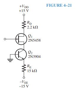
Question 4.8: Figure 4–21 shows a current-source biasing circuit. What is ...
Figure 4–21 shows a current-source biasing circuit. What is I_{D} ?

The blue check mark means that this solution has been answered and checked by an expert. This guarantees that the final answer is accurate.
Learn more on how we answer questions.
Learn more on how we answer questions.
You should recognize emitter bias for the bipolar junction transistor but with no base resistor. Since the base is connected directly to ground, the emitter voltage is -0.7 V due to the forward-biased base-emitter pn junction. This means that the voltage across R_{E} is 14.3 V and the current in R_{E} is constant. From Ohm’s law, find the emitter current as
I_{E} = \frac{V_{R_{E} } }{R_{E} } = \frac{14.3 V}{15 k\Omega } = 0.95 mA
This current is provided to the JFET. Therefore, I_{D} = 0.95 mA.
Related Answered Questions
Question: 4.14
Verified Answer:
The difference between the gate voltage and the ne...
Question: 4.12
Verified Answer:
On the data sheet, g_{m} is shown a...
Question: 4.11
Verified Answer:
(a) First, find the dc drain voltage.
V_{D}...
Question: 4.9
Verified Answer:
Since I_{D} = I_{DSS} = 12 mA, the ...
Question: 4.13
Verified Answer:
On the transconductance curve draw a line represen...
Question: 4.7
Verified Answer:
(a) Start with V_{G} because this v...
Question: 4.6
Verified Answer:
Plot the line representing a 2.0 kΩ resistor by se...
Question: 4.5
Verified Answer:
Typical of small-signal JFETs, the range of [latex...
Question: 4.4
Verified Answer:
V_{S} = I_{D} R_{S} = (5.0 mA)(220 ...
Question: 4.3
Verified Answer:
R_{IN} = \left|\frac{V_{GS} }{I_{GSS} } \ri...