Question 6.7: A nonhomogeneous beam having the dimensions shown in Fig. 1a......
A nonhomogeneous beam having the dimensions shown in Fig. 1a is constructed by gluing a thin aluminum plate to the top side of a square wood beam. Take E_1 ≡ E_{\text{alum.}} = 70 GPa and E_2 ≡ E_{\text{wood}} = 12 GPa.
Determine the maximum flexural stress in the aluminum and the maximum flexural stress in the wood when a moment M = 3 kN · m is applied in the manner indicated in Fig. 1b.

Learn more on how do we answer questions.
Plan the Solution We must use Eq. 6.20 to locate the neutral axis, and we can then use Eqs. 6.24 to compute the flexural stresses in the two materials.
E_1\bar{y}_1A_1 + E_2\bar{y}_2A_2 = 0 (6.20)
σ_{x1} = \frac{-ME_1y}{\bar{EI}}, σ_{x2} = \frac{-ME_2y}{\bar{EI}} Flexure Formulas (6.24)
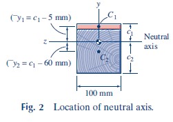
Neutral-Axis Location: The neutral axis of the beam is located at distance c_1, from the top of the beam, as indicated in Fig. 2. From Eq. 6.20.
E_1\bar{y}_1A_1 + E_2\bar{y}_2A_2 = 0(70 GPa)(1000 mm²)(c_1 – 5 mm)
+(12 GPa)(10 000 mm²)(c_1 – 60 mm) = 0
Then,
c_1 = 39.74 mm, c_2 = 70.26 mm
and
\bar{y}_1 = 34.74 mm, \bar{y}_2 = -20.26 mm
Moment of Inertia: Since the moments of inertia I_1 and I_2 are to be taken about the z axis (neutral axis), we must use the parallel-axis theorem.
I_1 = \frac{b_1h^3_1} {12} + A_1\bar{y}^2_1= \frac{(100 mm)(10 mm)^3} {12}+(100 mm)(10 mm)(34.74 mm)²
= 1.215(10^6) mm^4 = 1.215(10^6) mm^4 (10^3 mm/m)^{-4}
I_1 = 1.215(10^{-6}) mm^4Similarly,
I_2 = 12.439(10^{-6}) mm^4
Before calculating the flexural stresses we can check these moments of inertia by using the equation
I_z = I_1 + I_2 = 13.65(10^6) mm^4But,
I_z = (I_z)_{\begin{matrix} \text{area} \\ \text{above} \end{matrix}}+(I_z)_{\begin{matrix} \text{area} \\ \text{below} \end{matrix}}= \frac{1} {3} (100 mm)(39.74 mm)³ + \frac{1} {3}(100 mm)(70.26 mm)³
= 13.65(10^6) mm^4
Flexural Stresses: The flexural stresses in materials 1 and 2 are given by Eqs. 6.24, with \overline{EI} defined by Eq. 6.23.
\overline{EI} = (E_1I_1 + E_2I_2) (6.23)
\overline{EI} = E_1I_1 + E_2 I_2 = [70(10^9) N/m² ] [1.215 10^{-6} m^4 ]
=[12(10^9) N/m² ] [12.439(10^{-6}) m^4 ]
= 234.3(10³) N · m² = 234.3 kN · m²
Finally, the maximum stresses in materials 1 and 2, which occur at y = c_1 and y=-c_2, respectively, are
(σ_{x1})_{max} = \frac{-ME_1(c_1)} {\overline{EI}}= \frac{-(3 kN · m)(70 × 10^6 kN/m^2)(39.74 × 10^{-3} m)} {234.3 kN · m^2}
= -35.6(10³) kN/m² = -35.6 MPa
(σ_{x2})_{max} = \frac{-ME_2(-c_2)} {\overline{EI}}= \frac{-(3 kN · m)(12 × 10^6 kN/m^2)(-70.26 × 10^{-3} m)} {234.3 kN · m^2}
= 10.79(10³) kN/m² = 10.79 MPa
(σ_{x1})_{max} = -35.6 MPa, (σ_{x2})_{max} = 10.79 MPa
Review the Solution This is the type of problem where we should check our result at each major step, as we did for the moment of inertia.
We should expect the stiffer aluminum to experience higher stresses than those in the wood, and this is the case here.
This same problem is solved, in Example Problem 6.8, by the transformed-section method.