Question 6.16: A pipe conveying fluid over a narrow stream crossing must ac......
A pipe conveying fluid over a narrow stream crossing must act as a beam as well as a conduit, as indicated in Fig. 1.
Assuming that the ratio of mean diameter to wall thickness satisfies the requirement d/t \gg 1. determine the shear flow and shear stress distribution at a section due to the transverse shear force, V, at that section, Also, determine the maximum shear stress on the cross section, and express τ_{max} in terms of V/A.

Learn more on how do we answer questions.
Plan the Solution As noted in the preceding discussion of shear in closed, thin-wall beams, we should pick a free-body diagram that is symmetric about the xy-plane. Then we can apply the shear flow formula, Eq. 6.65, and the average shear formula, Eq. 6.68, to this free-body diagram.
q = \frac{VQ} {I} Shear-Flow Formula (6.65)
τ(x, s) = \frac{q(x, s)} {t(x, s)} (6.68)
Because this is a circular cross section, it is convenient to select a free-body diagram that is defined by radial cutting planes at angle θ either side of the xy-plane, as indicated in Fig. 2. In Fig. 2b there are two surfaces that have equal shear forces ΔH which serve to balance the net force (F_2 — F_1) due to the flexural stresses. Therefore, we get
2ΔH = F_2 – F_1 (1)
where, from the definition of shear flow
ΔH = qΔx (2)
Comparing Eq. (1) to Eq. 6.60, and following the same steps that were used to arrive at Eq. 6.65, we get
ΔH = F_2 – F_1 (6.60)
2q = \frac{VQ} {I} (3)
for the symmetric free-body diagram in Fig. 2. Here, as in Eq. 6.65,
Q = \int_{A^′} {y dA} = A^′\bar{y}^′ (4)
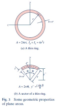
is the first moment, about the neutral axis, of the area acted on by the unbalanced flexural stresses, and I is the moment of inertia of the entire cross section about its neutral axis. The geometric properties for a thin ring and for a sector of a thin ring are shown in Fig. 3. Using the formulas in Fig. 3b, we have, for t \ll r,
Q = A^′\bar{y}^′ = 2r²t sin θ (5)
Combining the moment of inertia from Fig. 3a with Eqs. (3) and (5), we get
q = \frac{V(2r^2t \sin θ)}{(2\pi r^3t)} = \frac{V \sin θ} {\pi r} (6)
The average shear stress is obtained from the shear flow by using Eq. 6.68. Therefore,
τ = \frac{q} {t} = \frac{V \sin θ} {\pi rt} (7)
Figure 4 illustrates the distribution of shear flow (and shear stress).
The maximum shear stress is given by
τ_{max} = τ_{(θ=\pi /2)} = \frac{V} {\pi rt}Since the area of the cross section can be approximated by
A ≈ 2πrt
for a thin-wall pipe beam with t \ll r, the maximum shear stress is^{32}
τ_{max} = \frac{2V} {A} (8)
Review the Solution As a check on the expression that we obtained for q, Eq. (6). we can see if the resultant of this distribution is V. as it is supposed to be. The force on the elemental area highlighted in Fig. 4 is
dF = q ds = qr dθ
The vertical component, as shown on the insert in Fig. 4, is, therefore,
dF_y = qr sin θ dθ
So, due to symmetry, we have
F_y = 2 \int^{\pi}_{0} {qr \sin θ dθ}= \frac{2V} {\pi}\int^{\pi}_{0} { \sin^2 θ dθ}
= \frac{2V} {\pi}\left[ \frac{θ} {2}-\frac{1}{4}\sin^2 θ \right]^{\pi}_0 = V
Since the distribution looks “reasonable” (the shear flow has its maximum at the neutral axis and is zero on the plane of symmetry), and since it gives the correct resultant, we can assume that our answer is correct.