Question 5.11: A state of plane stress consists of a tensile stress σ0 = 8 ......
A state of plane stress consists of a tensile stress σ_0 = 8 ksi exerted on vertical surfaces and unknown shear stresses τ_0. Determine (a) the magnitude of the shear stress τ0 for which the maximum normal stress is 10 ksi, and (b) the corresponding maximum shear stress.
Given: Plane stress state.
Find: Shear stress τ_0; maximum shear stress.
Assume: Plane stress.

Learn more on how do we answer questions.
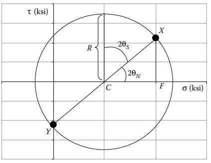
We will assume a sense (sign) for the unknown shear stress, and construct Mohr’s circle. The shearing stress τ_0 on faces normal to the x-axis tends to rotate the element clockwise, so we plot point X, whose coordinates are (σ_0, \ τ_0), above the σ-axis. We see that in our initial state, σ_{yy} is zero and that on faces normal to the y-axis τ_0 tends to rotate the element counterclockwise; thus, we plot point Y(0, τ_0), below the σ-axis.
Line XY passes through the center of our circle, at
\sigma_{\mathrm{av}}=\frac{1}{2}\left(\sigma_{x x}+\sigma_{y y}\right)=\frac{1}{2}(8+0)=4 \mathrm{ksi} .
We determine the radius R of the circle by observing that the maximum normal stress, given as 10 ksi, appears a distance R to the right of the circle’s center:
\begin{aligned} \sigma_1 & =\sigma_{\mathrm{av}}+R ,\\ R & =\sigma_1-\sigma_{\mathrm{av}} ,\\ R & =10 \mathrm{ksi}-4 \mathrm{ksi}=6 \mathrm{ksi}. \end{aligned}Now we have Mohr’s circle to work with. We see that the rotation required to get from our initial stress state (point X) to the principal stress state at (10 ksi, 0) is either clockwise 2θ_N as shown, or counterclockwise 360° − 2θ_N. We choose to work with the more manageable clockwise rotation, and consider the right triangle C F X.
\begin{aligned} \cos 2 \theta_N & =\frac{C F}{C X}=\frac{C F}{R}=\frac{4 \mathrm{ksi}}{6 \mathrm{ksi}} . \\ \theta_N & =-24.1^{\circ}. \end{aligned}This rotation, again, is clockwise, as reflected by the negative sign. The right triangle CFX also allows us to compute the unknown shear stress, τ_0, which is experienced at point X:
\tau_0=F X=R \sin 2 \theta_N=(6 \mathrm{ksi}) \sin 48.2^{\circ}=4.47 \mathrm{ksi}.The maximum shear stress is also apparent from Mohr’s circle. It is simply the radius of the circle, R:
\tau_{\max }=R=6 \mathrm{ksi}The corresponding normal stress at this stress state is σ_{av} = 4 ksi. Mohr’s circle indicates that to get from the initial stress state to the state of maximum shear stress, we must rotate the circle diameter XY counterclockwise by 2θ_S, or rotate the element itself by θ_S. It is clear from the circle that 2θ_S + |2θN| = 90°. Hence
2 \theta_S=90^{\circ}-\left|2 \theta_N\right|=90^{\circ}-48.2^{\circ}=41.8^{\circ} .With all this information in hand, we can draw properly oriented elements in each of the identified stress states.
Note: If we had originally assumed the opposite sense of the unknown τ_0, we would have obtained the same numerical answers, but the orientation of the elements would be as shown below.