Question 6.18: Consider again the bracket of Example Analysis 11 as shown i......
Consider again the bracket of Example Analysis 11 as shown in Figure a. As before, let the bracket be a relatively rigid “L-shape” member supported by rivets on its vertical side, and acting as a shelf on its horizontal portion. Assume further that the vertical support is rigid. Next, suppose a box B with weight W is to be placed on the shelf portion of the bracket as presented in Figure b. Let B be modeled as a homogeneous block with mass m. Suppose further that as B is being placed on the shelf it is dropped onto the shelf while it is only a small distance above the shelf as represented in Figure c. The dropped box causes a sudden, or “dynamic,” loading on the bracket.
Determine the stresses in the rivets due to the dynamic loading.


Learn more on how do we answer questions.
Observe in Figure a, and in the problem statement, that with the bracket and vertical support being rigid, the only elastic members are the rivets. If we assume further that the box is considerably heavier than the bracket, but not so heavy that the rivets are stretched beyond their elastic limits, then we can model the entire structure (the box, the bracket, the rivets, and the vertical support) as a linear mass-spring system.
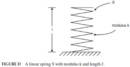
If we model the system as a linear mass-spring system, we can readily determine the requested rivet stresses, due to the dynamic loading, by using the elementary work-energy method. To see this, consider a massless linear spring S with length \ell and modulus k resting on a horizontal surface as represented in Figure d.
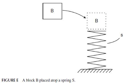
Next, imagine a block B with weight W and mass m (equal to W/g) to be placed atop S and then released when it is just a small distance above the spring as represented in Figures e and f. As the block B continues to fall, and as δ increases, the resistive force F exerted by S on B also increases according to the well-known relation:
F = k \delta (a)
As δ increases, the resistive force F of S also increases until it eventually becomes large enough to stop the fall of B. Let δ_{max} then be the maximum compression of S—that is, when S arrests the downward movement of B. Then from Eq. (a) the resistive force of S, when stopping B, reaches its maximum value F_{max} given by:
F_{max}= k \delta_{max} (b)
Recall now the work-energy principle which states that the work done on a system, or a part of a system, between two different configurations (or “states”) is equal to the change in kinetic energies of the system between these two states. Analytically, the work-energy principle may be written as:
W ork=\Delta KE (c)
where KE represents the kinetic energy.
By applying this principle to the block B we see that the work done on B between the time it is released atop S until its fall is stopped by S, is due to two forces: gravity (or weight W) and the spring force F. That is:
Work=Work_{gravity}= Work_{spring} (d)
The work done on B by gravity is simply the weight force: W (= mg) multiplied by the fall distance: δ_{max}. That is:
Work_{gravity}=W δ_{max} (e)
The work done on B by the spring force F (Work_{spring}) is a bit more detailled since F is proportional to the downward displacement δ as in Eq. (a). Therefore, Work_{spring} is the sum of the incremental work of F during the fall. That is:
Work_{spring}=\int\limits_{0}^{\delta _{max}}{} Fd\delta =-\int\limits_{0}^{\delta _{max}}{} k\delta d\deltaor
Work_{spring}=-(1/2)k\delta ^{2}_{max} (f)
where the negative sign arises since the spring force F on B is directed upward and thus \underline{opposite} opposite to the downward movement of B.
Just before B is released from rest atop S its kinetic energy is zero (B is at rest). Also, when the downward movement of B is arrested by S, its kinetic energy is zero. Therefore, the change in kinetic energies between the two states ΔKE is also zero. That is,
\Delta KE=0 (g)
By substituting from Eqs. (d), (e), (f), and (g) into Eq. (c) we have:
Work = 0 (h)
or
Work_{gravity}+Work_{spring}=0 (i)
or
W\delta _{max}-(1/2) k\delta ^{2}_{max}=0 (j)
or
k\delta _{max}=2W (k)
But from Eq. (b) we see that kδ_{max} is simply the maximum force F_{max} in the spring. Therefore, F_{max} is simply:
F_{max}=2W (l)
Equation (l) shows that the sudden application of the weight load has the same effect as a static load with twice the magnitude! This is a well-known result and widely used “rule of thumb” in structural dynamics.
In view of the result of Eq. (l) we can immediately determine the requested rivet stresses due to the dynamic loading. Recall from Example Analysis 11 that for a static weight load W, the stresses in the rivets are given by Eqs. (k) and (l) of that example as:
\sigma _{A}=Wb\left(d+e\right)/ \left(\pi r^{2}\right)\left[\left(d+e\right)^{2}+e^{2} \right] (m)
and
\sigma _{B}=Wbe/\left(\pi r^{2}\right)\left[\left(d+e\right)^{2}+e^{2} \right] (n)
where b, d, e, and r are dimensions of the bracket as shown in Figure h.
Therefore, replacing W by 2W in Eqs. (m) and (n) the requested dynamic rivet stresses are:
\sigma _{A}=2Wb\left(d+e\right)/ \left(\pi r^{2}\right)\left[\left(d+e\right)^{2}+e^{2} \right] (n)
and
\sigma _{B}=2Wbe/\left(\pi r^{2}\right)\left[\left(d+e\right)^{2}+e^{2} \right] (o)
Comment
Observe in obtaining the results in Eqs. (n) and (o) we did not need to obtain the deformations of the rivets, but instead we simply used the results of Example Analysis 24 for the static loading.