Question 9.6: Let us consider an experimental installation for heating and......
Let us consider an experimental installation for heating and DHW production located in the Laboratory for the Quality Control of Buildings (LCCE) of the Basque Government. It consists of a Stirling micro-cogeneration engine with an electric power of 1 kW and a thermal power in the form of hot water between 3.7 and 5 kW, which can provide additional thermal power of 20 kW by means of an auxiliary boiler. There is also a 28 kW condensing boiler for hot water. The DHW branch has a plate heat exchanger and a deposit of 1000 L. The heat generated for heating is dissipated in a fan coil with a three-way valve. The installation also has a hydraulic compensator, circulation pumps and distribution pipes, and 120 sensors that record the temperatures, pressures and flow rates of the different flows over time, see the diagram in Fig E.9.13.
The control of the installation is such that the Stirling has priority over the boiler so that it is the first component to activate when the temperature of the DHW tank drops below 60°C and until it reaches 70°C, or when there is heating demand. The auxiliary boiler will start working when, while the Stirling engine and the condensing boiler are on, the return temperature drops below 60°C.
Using the TRNSYS software, the heating and DHW demand profile for three terraced houses located in Vitoria was calculated. These calculated demand profiles are repro-duced faithfully by the installation control system, acting on the DHW valve and the three-way valve associated with the fan coil. With the data collected in a trial conduct-ed over 4 days, determine
(a) Equipment under consideration and functional analysis.
(b) Percentage of exergy destruction in each component.
(c) Avoidable and unavoidable exergy destruction.
(d) Endogenous and exogenous exergy destruction.
(e) Avoidable endogenous and avoidable exogenous exergy destruction and unavoidable endogenous and unavoidable exogenous exergy destruction in each component.
(f) Distribution of the avoidable endogenous and exogenous exergy destruction and unavoid-able endogenous and unavoidable exogenous exergy destruction throughout the whole of the installation.

Learn more on how do we answer questions.
(a) Fig. E.9.13 shows an outline of the installation. The figure also shows the equipment under consideration for the analysis, according to the criteria given below.
Before starting the analysis, the equipment to be considered needs to be chosen, and the functional analysis needs to be performed on each of them. Some components need to be considered together with others in order to assign them a productive process. For example, the outgoing manifold and the return manifold considered individually do not have a productive purpose, but if we consider them together, as a single component (equipment C), their productive purpose is the heating and DHW supply. Something similar happens with the separator and mixer (equipment V1) and with the three-way valve and the mixer, (equipment V2 and V3). Considered together they have a product which consists of DHW and heating supply, DHW only and heating only, respectively. In this way, we have selected the equipment that appears in Table E.9.10.
Once the equipment has been selected, using the experimental data from the trial, a grey box model was built for each one of them. To this end, we used the TYPE of TRNSYS that was considered most appropriate, and when incorporating the test data, parameters were adjusted to the model, so that the final model incorporates the inertias and describes the real behaviour of the equipment. This was done by inte-grating TRNSYS with MATLAB. This development can be found in greater detail in Picallo et al. 2017 [E.2].
Fig. E.9.14 shows the integration mode of these two pieces of software obtaining the model in the case of two components, the round-trip manifold (C), and the heat exchanger (HX).
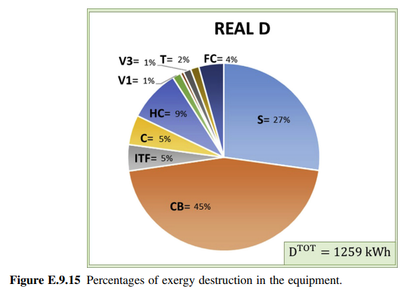
(b) Performing an exergy balance in each component gives the exergy destruction. Fig. E.9.15 shows the percentage of destruction in each component with respect to the total destruction. As can be seen in the equipment where there is combustion, the highest percentages are 27% for the Stirling engine and 46% for the condensing boiler. These differences are explained, on the one hand, because the condensing boiler has greater power and on the other, because the Stirling engine has a significantly better efficiency, as it simultaneously produces elec-tricity and hot water.
(c) Unavoidable exergy destruction is calculated for each component considering it in isolation and assuming the most favourable conditions. These conditions involve small temperature differences in heat transfer and small head losses, producing the same amount of product. We see, therefore, that the definition of these conditions is to some extent arbitrary and depends on the criteria and experience of the analyst. We will now detail the criteria that were used for each component in the installation.
- C/V1/V2/V3: Irreversibilities in these components are due to the mixture of flows with different temperatures and pressures. Therefore, it can be assumed that the control system acts in such a way that these differences are avoided so that the unavoidable destruction can be considered to be zero.
- AuxCB: The objective of this equipment is to guarantee adequate temperature at the inlet of the condensing boiler. Therefore, all irreversibilities can be avoided if this flow is in the proper state.
- D: Unavoidable exergy destruction is defined by the selection of the fan-coil with the highest efficiency in the market.
- HX: Unavoidable exergy destruction will correspond to an adiabatic heat exchanger, with minimum head losses and selecting the minimum temperature difference between the average thermodynamic temperature of the hot flow and the cold flow.
- HC/T: Since the greatest irreversibility in the tanks is due to the mixing of the hot and cold flows, tanks with the highest stratification and without heat losses should be sought. Although they have an important effect on the irreversibilities, both the filling and emptying temperatures are fixed, as well as the filling and emptying process, which is established by the DHW demand profile.
- S/CB: As we have said, the components in which combustion takes place are the ones that have the greatest exergy destruction. The causes of irreversibility are friction, diffu-sion, mixing, chemical reactions and heat transfer. Unavoidable exergy destruction is ob-tained by considering small head losses in the combustion chamber, complete combustion with the theoretical air (although this increases the adiabatic combustion temperature) and a minimum temperature difference in the heat transfer between the gases and the water.
For maintaining these conditions, the unavoidable exergy destruction of each component was calculated. Once this has been calculated, the avoidable exergy destruction is obtained by subtracting the unavoidable exergy destruction already calculated from the total exergy destruction. Fig. E.9.16 shows the values obtained for {D}_{i}^{U N} and {D}_{i}^{AV} for each component during the period of the test.
(d) The endogenous exergy destruction in equipment is part of the total exergy destruction that is due exclusively to the irreversibilities in that equipment. In order to calculate it, the recently developed method, known as the breakdown method, has been used, which consists in calculating the endogenous exergy destruction of a component, idealizing the behaviour of the rest of the installation’s equipment, while maintaining constant production. Fig. E.9.17 shows the application of the breakdown method for the calculation of the endog-enous exergy destruction in the Stirling engine S, in the component V2, in the hydraulic compensator HC and in the plate heat exchanger HX.
Once D_{i}^{E N} has been calculated for each component, the exogenous exergy destruction is calculated as the difference between the total exergy destruction and endogenous exergy destruction, which is,
Fig. E.9.18 shows the endogenous and exogenous irreversibilities of each of the components in the installation. As can be seen, the exogenous irreversibility decreases the closer the component is to the end of the energy chain. It is explained by the fact that, for a fixed production of heating and DHW, the equipment that is at the beginning of the energy chain needs to produce more to overcome the irreversibilities of the equipment that is further along the chain and therefore, will generate more irreversibilities.
It is of interest to know the effect of each component in the calculation of exoge-nous irreversibilities, for which, scenarios are drawn up in which two components work with their real efficiency and the rest of the equipment functions under ideal conditions, that is, with unit efficiency. In this way, the exergy destruction induced in the i-th equipment is calculated because the need to adapt to the irreversibilities that occur in equipment k, D_{k\to i}^{E X}. This calculation was made by subtracting the exergy destruction in the previous step from the new exergy destruction D_{ i}^{\prime} when all equip-ment except equipment i is ideal, which is
Fig. E.9.19 shows the contribution of other equipment in the exogenous exergy destruction of each component.
Once the exergy destruction due to each of the other components in the installation, \sum_{k=1,k\neq i}^{n}D_{k\to i}^{E X} has been calculated for equipment i, the effects induced when more than two components are considered must be taken into account. This is the term that is known as mexogenous exergy destruction and is calculated by subtracting the previous sum from the exogenous exergy destruction, which is
D_{i}^{M E X}=D_{i}^{E X}-\sum_{k=1,k\neq i}^{n}D_{k\to i}^{E X}(e) Once the avoidable and unavoidable, endogenous and exogenous exergy destructions have been calculated, we combine them to obtain, for each component: the reduction in exergy destruction that can be introduced by improvements in the equipment D_{i}^{A V, E N}; the reduction in exergy destruction that can be made by improvements in the other components and the structure of the installation D_{i}^{A V, E X}; the unavoidable exergy destruction because of the equipment itself D_{i}^{UN, E N} and that due to the structural restrictions of the installation and to the technical limitations of the other equipment D^{UN, E X} Fig. E.9.20 shows the results obtained for each component.
(f) Finally, Fig. E.9.21 gives the percentages of the four types of exergy destruction in the installation as a whole. As can be seen, 76% of the exergy destruction is unavoidable, of which 30% is due to the limitations of the equipment and 46% to the structural restrictions in the interrelations of the equipment
Table E.9.10 List of equipment considered for analysis.
| Name | Description |
| S | Stirling cogeneration engine |
| CB | Condensing boiler |
| ITF | CB inlet temperature controller |
| C | Outgoing and return manifold |
| HC | Hydraulic compensator |
| V1 | DHW and heating mixer and separator |
| V2 | HX mixer and separator |
| HX | Heat exchanger |
| V3 | Heating mixer and separator |
| T | Thermal energy storage |
| FC | Fan Coil |