Question 9.28: Using Kern's method, design a shell and tube heat exchanger ......
Using Kern’s method, design a shell and tube heat exchanger to cool 30 kg/s of butyl alcohol from 370 to 315 K using treated water as the coolant. The water will enter at 300 K and leave at 315 K.
Learn more on how do we answer questions.
Since it is corrosive, the water will be passed through the tubes.
At a mean temperature of 0.5(370 + 315) = 343 K, from Table 3, Appendix A1, the thermal capacity of butyl alcohol = 2.90 kJ/kg K and hence:
Heat load = (30 x 2.90)(370 – 315) = 4785 kW
If the heat capacity of water is 4.18 kJ/kg K, then:
Flow of cooling water = 4785/(4.18(315 – 300)) = 76.3 kg/s
The logarithmic mean temperature difference,
\theta _{m} = [(370 – 315) – (315 – 300)]/ln[(370 – 315)/(315 – 300)] = 30.7 deg K
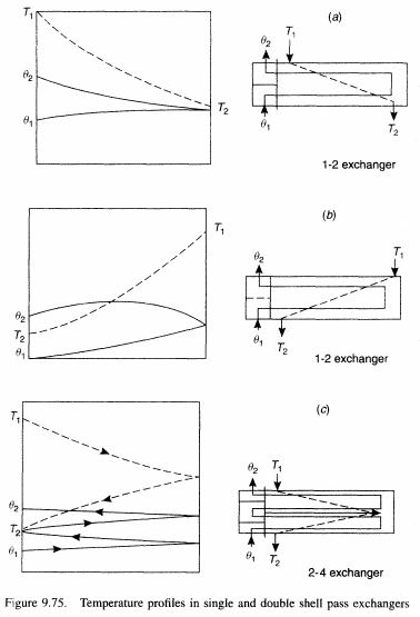
With one shell-side pass and two tube-side passes, then from equation 9.213:
X={\frac{\theta_{2}-\theta_{1}}{T_{1}-\theta_{1}}}\quad{\mathrm{and}}\quad Y={\frac{T_{1}-T_{2}}{\theta_{2}-\theta_{1}}} (9.213)
X = (370 – 315)/(315 – 300) = 3.67 and Y = (315 – 300)/(370 – 300) = 0.21
and from Figure 9.75:
F = 0.85 and F\theta _{m} = (0.85 x 30.7) = 26.1 deg K
From Table 9.17, an estimated value of the overall coefficient is U = 500 W/m²K and hence, the provisional area, from equation 9.212, is:
Q = UAF\theta _{m} (9.212)
A = (4785 x 10³)/(26.1 x 500) = 367 m²
It is convenient to use 20 mm OD, 16 mm ID tubes, 4.88 m long which, allowing for the tube-sheets, would provide an effective tube length of 4.83 m. Thus:
Surface area of one tube = π(20/1000) = 0.303 m²
and: Number of tubes required = (367/0.303) = 1210
With a clean shell-side fluid, 1.25 triangular pitch may be used and, from equation 9.211:
Number of tubes, N_{t}=a(d_{b}/d_{o})^{b} (9.211)
1210=0.249(d_{b}/20)^{2.207}from which: d_{b} = 937 mm
Using a split-ring floating head unit, then, from Figure 9.71. the diametrical clearance between the shell and the tubes = 68 mm and:
Shell diameter, d_{s} = (937 + 68) = 1005 mm
which approximates to the nearest standard pipe size of 1016 mm.
Tube-side coefficient
The water-side coefficient may now be calculated using equation 9.218, although here, use will be made of the j_{h} factor.
Nu=(h d/k)= j_{h}R e P r^{0.33}(\mu/\mu_{s})^{-0.14} (9.218)
Cross-sectional area of one tube = (π/40) x 16² = 201 mm²
Number of tubes/pass = (1210/2) = 605
Thus: Tube-side flow area = (605 x 201 x 10^{-6}) = 0.122 m²
Mass velocity of the water = (76.3/0.122) = 625 kg/m²s
Thus, for a mean water density of 995 kg/m³:
Water velocity, u = (625/995) = 0.63 m/s
At a mean water temperature of 0.5(315 + 300) = 308 K, viscosity, μ = 0.8 mN s/m² and thermal conductivity, k = 0.59 W/m K.
Thus:
Re = duρ/μ = (16 x 10^{-3} x 0.63 x 995)/(0.8 x 10^{-3}) = 12540
Pr = C_{p}μ/k = (4.18 x 10³ x 0.8 x 10^{-3})/0.59 = 5.67
l/d_{i} = 4.83/(16 x 10^{-3}) = 302
Thus, from Figure 9.77, j_{h} = 3.7 x 10^{-3}, and, in equation 9.218, neglecting the viscosity term:
Nu=(h d/k)= j_{h}R e P r^{0.33}(\mu/\mu_{s})^{-0.14} (9.218)
(h_{i}\times16\times10^{-3})/0.59=(3.7\times10^{-3}\times12540\times5.67^{0.33})and: h_{i} = 3030 W/m²K
Shell-side coefficient
The baffle spacing will be taken as 20 per cent of the shell diameter or (1005 x 20/100) = 201 mm
The tube pitch = (1.25 x 20) = 25 mm and, from equation 9.226:
A_{s}=d_{s}l_{B}C^{\prime}/Y (9.226)
Cross-flow area, A_{s} = [(25 – 20)/25](1005 x 201 x 10^{-6}) = 0.040 m²
Thus: Mass velocity in the shell, G_{s} = (30/0.040) = 750 kg/m²s
From equation 9.228:
For square pitch : d_{e}=4(Y^{2}-\pi d_{o}^{2})4/\pi d_{0}=\;1.27(Y^{2}-0.785d_{o}^{2})/d_{o}(9.277)
and for triangular pitch : d_{e}=4[(0.87Y\times Y/2)-(0.5\pi d_{o}^{2}/4]/(\pi d_{o}/2)
=1.10(Y^{2}-0.917d_{o}^{2})/d_{o} (9.228)
Equivalent diameter, d_{e} = 1.10[25² – (0.917 x 20²)]/20 = 14.2 mm
At a mean shell-side temperature of 0.5(370 + 315) = 343 K, from Appendix A1:
density of butyl alcohol, ρ = 780 kg/m³, viscosity, μ = 0.75 mN s/m², heat capacity, C_{p} = 3.1 kJ/kg K and thermal conductivity, k = 0. 16 W/m K.
Thus, from equation 9.229:
R e_{s}=G_{s}^{\prime}d_{e}/\mu=u_{s}d_{e}\rho/\mu (9.229)
Re = G_{s}d_{e}/μ = (750 x 14.2 x 10^{-3})/(0.75 x 10^{-3}) = 14200
Pr = C_{p}μ/k = (3.1 x 10³ x 0.75 x 10^{-3})/0.16 = 14.5
Thus, with a 25 per cent segmental cut, from Figure 9.81: j_{h} = 5.0 x 10^{-3}
Neglecting the viscosity correction term in equation 9.230:
N u=(h_{s}d_{e}/k_{f})=j_{h}R e P r^{0.33}(\mu/\mu_{s})^{0.14} (9.230)
(h_{s}\times14.2\times10^{-3})/0.16=5.0\times10^{-3}\times14200\times14.5^{0.33}and: h_{s} = 1933 W/m²K
The mean butanol temperature = 343 K, the mean water temperature = 308 K and hence the mean wall temperature may be taken as 0.5(343 + 308) = 326 K at which \mu _{s} = 1.1 mN s/m²
Thus: (\mu/\mu_{s})^{0.14}=(0.75/1.1)^{0.14}=0.95
showing that the correction for a low viscosity fluid is negligible.
Overall coefficient
The thermal conductivity of cupro-nickel alloys = 50 W/m K and, from Table 9.16, scale resistances will be taken as 0.00020 m²K/W for the water and 0.00018 m²K/W for the organic.
Based on the outside area, the overall coefficient is given by:
1/U=1/h_{o}+R_{o}+x_{w}/k_{w}+R_{i}/(d_{o}/d_{i})+(1/h_{i})(d_{o}/d_{i})= (1/1933) + 0.00020 + [0.5(20 – 16) x 10^{-3}/50] + (0.00015 x 20)/16 + 20/(3030 x 16)
= 0.00052 + 0.00020 + 0.00004 + 0.000225 + 0.00041 = 0.00140 m²K/W
and: U = 717 W/m²K
which is well in excess of the assumed value of 500 W/m²K.
Pressure drop
On the tube-side, Re = 12450 and from Figure 9.78, j_{f} = 4.5 x 10^{-3}
Neglecting the viscosity correction term, equation 9.225 becomes:
-\Delta P_{total}=N_{P}[4j_{f}(l/d_{i})(\mu/\mu_{s})^{m}+1.25](\rho u^{2}) (9.225)
ΔP_{t} = 2(4 x 4.5 x 10^{-3}(4830/16) + 1.25)(995 x 0.63²) = 5279 N/m² or 5.28 kN/m²
which is low, permitting a possible increase in the number of tube passes. On the shell-side, the linear velocity, (G_{s}/ρ) = (750/780) = 0.96 m/s
From Figure 9.82, when Re = 14200, j _{f} = 4.6 x 10^{-2}
Neglecting the viscosity correction term, in equation 9.231:
-\Delta P_{s}=4j_{f}(d_{s}/d_{e})(l/l_{B})(\rho u_{s}^{2})(\mu/\mu_{s})^{-0.14} (9.231)
– ΔP_{s} = (4 x 4.6 x 10^{-2})(1005/14.2)(4830/201)(780 x 0.96²)
= 224950 N/m² or 225 kN/m²
This value is very high and thought should be given to increasing the baffle spacing. If this is doubled, this will reduce the pressure drop by approximately (1/2)² = 1/4 and:
– ΔP_{s} = (225/4) = 56.2 kN/m² which is acceptable.
Since h_{o}\propto R e^{0.8}\propto u^{0.8}
h_{o}=1933(1/2)^{0.8}=1110\ \mathrm{W/m^{2}K}which gives an overall coefficient of \underline{\underline{561\ W/m^{2}K}} which is still in excess of the assumed value of 500 W/m²K.
| Table 9.16. Thermal resistances of scale deposits from various fluids | |||||
| m²K/kW | ft²h°F/Btu | m²K/kW | ft²h°F/Btu | ||
| Water* | Steam | ||||
| distilled | 0.09 | 0.0005 | good quality, oilfree | 0.052 | 0.0003 |
| sea | 0.09 | 0.0005 | |||
| clear river | 0.21 | 0.0012 | poor quality, oilfree | 0.09 | 0.0005 |
| untreated cooling tower | 0.58 | 0.0033 | |||
| treated cooling tower | 0.26 | 0.0015 | exhaust from reciprocating engines | 0.18 | 0.001 |
| treated boiler feed | 0.26 | 0.0015 | |||
| hard well | 0.58 | 0.0033 | Liquids | ||
| treated brine | 0.27 | 0.0015 | |||
| Gases | organics | 0.18 | 0.001 | ||
| air | 0.25-0.50 | 0.0015-0.003 | fuel oils | 1.0 | 0.006 |
| solvent vapours | 0.14 | 0.0008 | tars | 2.0 | 0.01 |
*For a velocity of 1 m/s (≈ 3 ft/s) and temperatures of less than 320 K (122°F)
| Table 9.17. Approximate overall heat transfer coefficients U for shell and tube equipment | |||
| Overall U | |||
| Hot side | Cold side | W/m²K | Btu/h ft² °F |
| Condensers | |||
| Steam (pressure) | Water | 2000-4000 | 350-750 |
| Steam (vacuum) | Water | 1700-3400 | 300-600 |
| Saturated organic solvents (atmospheric) | Water | 600-1200 | 100-200 |
| Saturated organic solvents (vacuum some non-condensable) | Water -brine | 300-700 | 50-120 |
| Organic solvents (atmospheric and high non-condensable) | Water -brine | 100-500 | 20-80 |
| Organic solvents (vacuum and high non-condensable) | Water -brine | 60-300 | 10-50 |
| Low boiling hydrocarbons (atmospheric) | Water | 400-1200 | 80-200 |
| High boiling hydrocarbons (vacuum) | Water | 60-200 | 10-30 |
| Heaters | |||
| Steam | Water | 1500-4000 | 250-750 |
| Steam | Light oils | 300-900 | 50-150 |
| Steam | Heavy oils | 60-400 | 10-80 |
| Steam | Organic solvents | 600-1200 | 100-200 |
| Steam | Gases | 30-300 | 5-50 |
| Dowtherm | Gases | 20-200 | 4-40 |
| Dowtherm | Heavy oils | 50-400 | 8-60 |
| Evaporators | |||
| Steam | Water | 2000-4000 | 350-750 |
| Steam | Organic solvents | 600-1200 | 100-200 |
| Steam | Light oils | 400-1000 | 80-180 |
| Steam | Heavy oils (vacuum) | 150-400 | 25-75 |
| Water | Refrigerants | 400-900 | 75-150 |
| Organic solvents | Refrigerants | 200-600 | 30-100 |
| Heat exchangers (no change of state) | |||
| Water | Water | 900-1700 | 150-300 |
| Organic solvents | Water | 300-900 | 50-150 |
| Gases | Water | 20-300 | 3-50 |
| Light oils | Water | 400-900 | 60-160 |
| Heavy oils | Water | 60-300 | 10-50 |
| Organic solvents | Light oils | 100-400 | 20-70 |
| Water | Brine | 600-1200 | 100-200 |
| Organic solvents | Brine | 200-500 | 30-90 |
| Gases | Brine | 20-300 | 3-50 |
| Organic solvents | Organic solvents | 100-400 | 20-60 |
| Heavy oils | Heavy oils | 50-300 | 8-50 |