Question 11.6: 180,000 lb/h of a saturated vapor consisting of 30 mole perc...
180,000 lb/h of a saturated vapor consisting of 30 mole percent n-butane and 70 mole percent n-pentane are to be condensed at a pressure of 75 psia. The condensing range at feed conditions is from 183.5ºF to 168ºF, and the enthalpy difference between saturated vapor and saturated liquid is 143 Btu/lbm. Cooling water is available at 85ºF and 60 psia. Tubing material is specified to be 90/10 copper–nickel alloy (k = 30 Btu/h . ft .ºF), and a fouling factor of 0.001 h . ft².ºF/Btu is recommended for the cooling water. Maximum pressure drops of 5 psi for the hydrocarbon stream and 10 psi for the coolant are specified. Physical properties of the feed and condensate are given in the table below. The viscosity of the condensate can be estimated using the following equation
\mu_{L}( CP )=0.00941 \exp \left[1668 / T\left({ }^{\circ} R \right)\right]
The other condensate properties may be assumed constant at the tabled values. Design a condenser for this service using plain (un-finned) tubes.
| Property | Feed | Condensate |
| C_{P}\left(\text { Btu/lbm } \cdot{ }^{\circ} F \right) | 0.486 | 0.61 |
| k (Btu/h . ft .º F) | 0.0119 | 0.057 |
| μ (cp) | 0.0085 | |
| ρ (lbm/ft³) | 0.845 | 35.5 |
| Pr | 0.84 |
Learn more on how we answer questions.
Make initial specifications.
(i) Fluid placement
A horizontal shell-side condenser will be used. Therefore, the condensing vapor is placed in the shell and cooling water in the tubes.
(ii) Shell and head types
An E-shell unit is specified since it is generally the most economical type of condenser. The difference between the inlet temperatures of the two streams is nearly 100F at design conditions, and could be significantly higher if the temperature of the cooling water decreases during cold weather. Therefore, U-tubes are specified to allow for differential thermal expansion. Thus, an AEU exchanger is specified.
(iii) Tubing
For water service, 3/4-in., 16-BWG tubes are selected with a length of 16 ft.
(iv) Tube layout
Since the shell-side fluid is clean, triangular pitch is specified. A tube pitch of either 15/16 or 1.0 in. can be used. The smaller value is selected because it provides more heat-transfer surface for a given shell size. (See tube-count tables in Appendix C.) (tables C.1, C.2, C.3, C.4, C.5, C.6, C.7 and C.8)
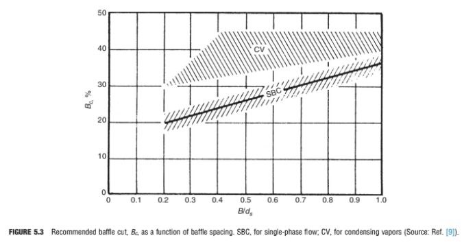
(v) Baffles
Segmental baffles with a spacing of 0.4 times the shell diameter and a cut of 35% are appropriate for a condensing vapor (see Figure 5.3).
(vi) Sealing strips
The bundle-to-shell clearance in U-tube exchangers is generally small. However, impingement protection is required for a condenser, and some tubes will have to be omitted from the bundle to provide adequate flow area above the impingement plate for the entering vapor. Depending on the size of the resulting gap in the tube bundle, sealing strips may be needed to block the bundle bypass flow.
(vii) Construction materials
The 90/10 cupro–nickel alloy specified for the tubes will provide corrosion resistance and allow a maximum water velocity of 10 ft/s (Table 5.B1). For compatibility, this material is also specified for the tubesheets. Plain carbon steel is adequate for the shell, heads, and all other components.
(b) Energy balances.
The duty is calculated using the given enthalpy difference between saturated vapor and saturated liquid. Condensate subcooling is neglected, as is the effect of pressure drop on saturation temperature:
Neither the outlet temperature nor the flow rate of the cooling water is specified in this problem. The outlet temperature is frequently limited to 110ºF to 125ºF in order to minimize fouling due to deposition of minerals contained in the water. Economic considerations are also involved, since a higher outlet temperature reduces the amount of cooling water used (which tends to lower the operating cost), while also lowering the mean temperature difference in the exchanger (which tends to increase the capital cost). For the purpose of this example, an outlet temperature of 120ºF will be used, giving an average water temperature of 102.5ºF. The properties of water at this temperature are as follows:
| Property | Water at 102.5 ºF |
| C_{P}\left(\text { Btu/lbm } \cdot{ }^{\circ} F \right) | 1 |
| k (Btu/h . ft .ºF) | 0.37 |
| μ (cp) | 0.72 |
| ρ (lbm/ft³) | 0.99 |
| Pr | 4.707 |
The cooling water flow rate is obtained from the energy balance:
q=25.74 \times 10^{6}=\left(\dot{m} C_{p} \Delta T\right)_{\text {water }}=\dot{m}_{\text {water }} \times 1.0 \times 35\dot{m}_{\text {water }}=735,429 lbm / h
(c) Mean temperature difference.
Since the condensing curve for this system (Figure 11.16) is approximately linear, the mean temperature difference is estimated as follows
\left(\Delta T_{\ln }\right)_{c f}=\frac{83-63.5}{\ln (83 / 63.5)}=72.8^{\circ} F
R=\frac{T_{a}-T_{b}}{t_{b}-t_{a}}=\frac{183.5-168}{120-85}=0.443
P=\frac{t_{b}-t_{a}}{T_{a}-t_{a}}=\frac{120-85}{183.5-85}=0.355
From Figure 3.14, F ≅ 0.98. Therefore,
\Delta T_{m} \cong 0.98 \times 72.8=71.3^{\circ} F(d) Approximate overall heat-transfer coefficient.
From Table 3.5, for a condenser with low-boiling hydrocarbons on the shell side and cooling water on the tube side, 80 ≤ U_{D} ≤ 200 Btu/h. ft².ºF. Taking the mid-range value gives U_{D} = 140 Btu/h . ft².ºF.
TABLE 3.5 Typical Values of Overall Heat-Transfer Coefficients in Tubular Heat Exchangers. U = Btu/h ft².ºF.
| Shell Side | Tube Side | Design U | Includes Total Dirt |
| Liquid–liquid media | |||
| Aroclor 1248 | Jet fuels | 100–150 | 0.0015 |
| Cutback asphalt | Water | 10–20 | 0.01 |
| Demineralized water | Water | 300–500 | 0.001 |
| Ethanol amine (MEA or | Water or DEA, or | 140–200 | 0.003 |
| DEA) 10–25% solutions | MEA solutions | ||
| Fuel oil | Water | 15–25 | 0.007 |
| Fuel oil | Oil | 10–15 | 0.008 |
| Gasoline | Water | 60–100 | 0.003 |
| Heavy oils | Heavy oils | 10–40 | 0.004 |
| Heavy oils | Water | 15–50 | 0.005 |
| Hydrogen-rich reformer stream | Hydrogen-rich reformer stream | 90–120 | 0.002 |
| Kerosene or gas oil | Water | 25–50 | 0.005 |
| Kerosene or gas oil | Oil | 20–35 | 0.005 |
| Kerosene or jet fuels | Trichloroethylene | 40–50 | 0.0015 |
| Jacket water | Water | 230–300 | 0.002 |
| Lube oil (low viscosity) | Water | 25–50 | 0.002 |
| Lube oil (high viscosity) | Water | 40–80 | 0.003 |
| Lube oil | Oil | 11–20 | 0.006 |
| Naphtha | Water | 50–70 | 0.005 |
| Naphtha | Oil | 25–35 | 0.005 |
| Organic solvents | Water | 50–150 | 0.003 |
| Organic solvents | Brine | 35–90 | 0.003 |
| Organic solvents | Organic solvents | 20–60 | 0.002 |
| Tall oil derivatives, vegetable oil, etc. | Water | 20–50 | 0.004 |
| Water | Caustic soda solutions (10–30%) | 100–250 | 0.003 |
| Water | Water | 200–250 | 0.003 |
| Wax distillate | Water | 15–25 | 0.005 |
| Wax distillate | Oil | 13–23 | 0.005 |
| Condensing vapor-liquid media | |||
| Alcohol vapor | Water | 100–200 | 0.002 |
| Asphalt (450ºF) | Dowtherm vapor | 40–60 | 0.006 |
| Dowtherm vapor | Tall oil and derivatives | 60–80 | 0.004 |
| Dowtherm vapor | Dowtherm liquid | 80–120 | 0.0015 |
| Gas-plant tar | Steam | 40–50 | 0.0055 |
| High-boiling hydrocarbons V | Water | 20–50 | 0.003 |
| Low-boiling hydrocarbons A | Water | 80–200 | 0.003 |
| Hydrocarbon vapors (partial condenser) | Oil | 25–40 | 0.004 |
| Organic solvents A | Water | 100–200 | 0.003 |
| Organic solvents high NC, A | Water or brine | 20–60 | 0.003 |
| Organic solvents low NC, V | Water or brine | 50–120 | 0.003 |
| Kerosene | Water | 30–65 | 0.004 |
| Kerosene | Oil | 20–30 | 0.005 |
| Naphtha | Water | 50–75 | 0.005 |
| Naphtha | Oil | 20–30 | 0.005 |
| Stabilizer reflux vapors | Water | 80–120 | 0.003 |
| Steam | Feed water | 400–1000 | 0.0005 |
| Steam | No. 6 fuel oil | 15–25 | 0.0055 |
| Steam | No. 2 fuel oil | 60–90 | 0.0025 |
| Sulfur dioxide | Water | 150–200 | 0.003 |
| Tall-oil derivatives, vegetable oils (vapor) | Water | 20–50 | 0.004 |
| Water | Aromatic vapor-stream | 40–80 | 0.005 |
| azeotrope | |||
| Gas-liquid media | |||
| Air, N_2, etc. (compressed) | Water or brine | 40–80 | 0.005 |
| Air, N_2, etc., A | Water or brine | 10–50 | 0.005 |
| Water or brine | Air, N_2 (compressed) | 20–40 | 0.005 |
| Water or brine | Air, N_2, etc., A | 5–20 | 0.005 |
| Water | Hydrogen containing natural–gas mixtures | 80–125 | 0.003 |
| Vaporizers | |||
| Anhydrous ammonia | Steam condensing | 150–300 | 0.0015 |
| Chlorine | Steam condensing | 150–300 | 0.0015 |
| Chlorine | Light heat-transfer oil | 40–60 | 0.0015 |
| Propane, butane, etc. | Steam condensing | 200–300 | 0.0015 |
| Water | Steam condensing | 250–400 | 0.0015 |
NC: non-condensable gas present; V: vacuum; A: atmospheric pressure.
Dirt (or fouling factor) units are (h) (ft²) (ºF)/Btu
(e) Heat-transfer area and number of tubes
A=\frac{q}{U_{D} \Delta T_{m}}=\frac{25.74 \times 10^{6}}{140 \times 71.3}=2579 ft ^{2}n_{t}=\frac{A}{\pi D_{o} L}=\frac{2579}{\pi(0.75 / 12) \times 16}=821
(f) Number of tube passes.
D_{i} = 0.620 in. = 0.0517 ft (Table B.1)
R e=\frac{4 \dot{m}\left(n_{p} / n_{t}\right)}{\pi D_{i} \mu}=\frac{4 \times 735,429\left(n_{p} / 821\right)}{\pi \times 0.0517 \times 0.72 \times 2.419}=12,666 n_{p}Therefore, two tube passes will suffice to give fully turbulent flow in the tubes. Checking the fluid velocity,
V=\frac{\dot{m}\left(n_{p} / n_{t}\right)}{\rho \pi D_{i}^{2} / 4}=\frac{(735,429 / 3600)(2 / 821)}{0.99 \times 62.43 \times \pi(0.0517)^{2} / 4}=3.84 ft / sThe velocity is acceptable, and therefore two passes will be used. (Note that four passes could also be used, giving a velocity of about 7.7 ft/s.)
(g) Shell size and tube count.
From Table C.2, the closest count is 846 tubes in a 31-in. shell.
(h) Required overall coefficient.
(i) Calculate h_{i} assuming Φ_{i} = 1.0.
R e=\frac{4 \dot{m}\left(n_{p} / n_{t}\right)}{\pi D_{i} \mu}=\frac{4 \times 735,429(2 / 846)}{\pi \times 0.0517 \times 0.72 \times 2.419}=24,584h_{i}=\left(k / D_{i}\right) \times 0.023 R e^{0.8} \operatorname{Pr}^{1 / 3}\left(\mu / \mu_{w}\right)^{0.14}
=(0.37 / 0.0517) \times 0.023(24,584)^{0.8}(4.707)^{1 / 3} \times 1.0
h_{i}=898 Btu / h \cdot ft ^{2} \cdot{ }^{\circ} F
(j) Calculate h_{0}
The basic Nusselt theory will be used to obtain a conservative estimate for the condensing heat-transfer coefficient. A tube wall temperature of 125º F is assumed to start the calculation. The average film temperature is calculated using the average vapor temperature of 175.75ºF:
The condensate viscosity at this temperature is:
\mu_{L}=0.00941 \exp [1668 /(137.7+460)]=0.153 cpThe modified condensate loading is calculated from Equation (11.41):
\Gamma^{*}=\frac{W}{L n_{t}^{2 / 3}}=\frac{180,000}{16(846)^{2 / 3}}=125.77 lbm / h \cdot ftThe heat-transfer coefficient is given by Equation (11.40):
h_{o}=1.52\left[\frac{k_{L}^{3} \rho_{L}\left(\rho_{L}-\rho_{V}\right) g}{4 \mu_{L} \Gamma^{*}}\right]^{1 / 3}=1.52\left[\frac{(0.057)^{3} \times 35.5(35.5-0.845) \times 4.17 \times 10^{8}}{4 \times 0.153 \times 2.419 \times 125.77}\right]^{1 / 3}h_{o}=121 Btu / h \cdot ft ^{2} \cdot{ }^{\circ} F
The shell-side coefficient is less than U_{r e q}, indicating that the condenser is severely under-sized. Therefore, no further calculations will be made with the initial configuration.
The low value of ho suggests that the value of U_{D} is likely to be less than 100 Btu/h . ft².ºF. The number of tubes needed to give U_{r e q} a value of, say, 90 Btu/h h . ft².ºF is:
With this many tubes, four tube passes will be required to keep the water velocity above 3 ft/s. Referring to the tube-count table, a 39-in. shell containing 1336 tubes is selected for the next trial.
Second Trial
(a) Required overall coefficient.
(b) Calculate h_{i} assuming \phi_{i} = 1.0.
R e=\frac{4 \dot{m}\left(n_{p} / n_{t}\right)}{\pi D_{i} \mu}=\frac{4 \times 735,429(4 / 1336)}{\pi \times 0.0517 \times 0.72 \times 2.419}=31,135h_{ i }=\left(k / D_{i}\right) \times 0.023 R e^{0.8} \operatorname{Pr}^{1 / 3}\left(\mu / \mu_{w}\right)^{0.14}
=(0.37 / 0.0517) \times 0.023(31,135)^{0.8}(4.707)^{1 / 3} \times 1.0
h_{i}=1085 Btu / h \cdot ft ^{2} \cdot{ }^{\circ} F
(c) Calculate h_{0}.
As before, a wall temperature of 125ºF is assumed, giving an average film temperature of 137.7ºF, at which μ_{L} = 0.153 cp.
h_{0}=1.52\left[\frac{(0.057)^{3} \times 35.5(35.5-0.845) \times 4.17 \times 10^{8}}{4 \times 0.153 \times 2.419 \times 92.74}\right]^{1 / 3}
h_{0}=134 Btu / h \cdot ft ^{2} \cdot{ }^{\circ} F
(d) Calculate T_{w} and T_{f} .
T_{w}=\frac{h_{i} t_{a v e}+h_{o}\left(D_{o} / D_{i}\right) T_{a v e}}{h_{i}+h_{o}\left(D_{o} / D_{i}\right)}=\frac{1085 \times 102.5+134(0.75 / 0.62) \times 175.75}{1085+134(0.75 / 0.62)}T_{w}=112^{\circ}F
T_{f}=0.75 \times 112+0.25 \times 175.75=128^{\circ}F
(e) Recalculate h_{0} .
The value of \mu_{L} at 128ºF is:
The corresponding value of h_{0} is:
h_{0}=1.52\left[\frac{(0.057)^{3} \times 35.5(35.5-0.845) \times 4.17 \times 10^{8}}{4 \times 0.161 \times 2.419 \times 92.74}\right]^{1 / 3}=132 Btu / h \cdot ft ^{2} \cdot{ }^{\circ} FSince this value is close to the previous one, no further iterations are required.
(f) Viscosity correction factor for cooling water.
Since the tube wall temperature is close to the bulk water temperature, the viscosity correction factor is neglected.
(g) Overall coefficient.
The recommended fouling factor for the cooling water was given in the problem statement as 0.001 h . ft².ºF/Btu. Since the condensing vapor is a very clean stream, a fouling factor of 0.0005 h . ft².ºF/Btu is appropriate. Thus,
=\left[\frac{0.75}{1085 \times 0.62}+\frac{(0.75 / 12) \ln (0.75 / 0.62)}{2 \times 30}+\frac{1}{132}+\frac{0.001 \times 0.72}{0.62}+0.0005\right]^{-1}
U_{D}=94 Btu / h \cdot ft ^{2} \cdot{ }^{\circ} F
(h) Correction for sensible heat transfer.
The effect of interfacial shear was neglected in calculating h_{0}, which will more than offset the effect of sensible heat transfer. Hence, this step could be omitted, but is included here to illustrate the procedure. The rate of sensible heat transfer is estimated using Equation (11.73). For convenience, the heat capacity at vapor inlet conditions is used as an approximation for \bar{C}_{P, V} :
=0.5 \times 0.486 \times 180,000(183.5-168)
q_{ sen }=677,970 Btu / h
q_{ sen } / q_{T o t}=677,970 / 25.74 \times 10^{6} \cong 0.026
The Simplified Delaware method will be used to calculate h_{V}. Since the baffle cut is greater than 20%, this method will tend to overestimateh_{V}. However, the safety factor built into the method will help to compensate for this error:
B=0.4 d_{5}=0.4 \times 39=15.6 \text { in. }C^{\prime}=P_{T}-D_{0}=15 / 16-0.75=0.1875 in .
a_{5}=\frac{d_{5} C^{\prime} B}{144 P_{T}}=\frac{39 \times 0.1875 \times 15.6}{144 \times 15 / 16}=0.845 ft ^{2}
D_{e}=0.55 / 12=0.04583 ft \quad \text { (from Figure 3.17) }
The average vapor flow rate of 90,000 lb/h is used to calculate h_{V}. Physical properties of the vapor are taken at inlet conditions for convenience
G=\dot{m} / a_{5}=90,000 / 0.845=106,509 lbm / h \cdot ft ^{2}R e=\frac{D_{e} G}{\mu_{V}}=\frac{0.04583 \times 106,509}{0.0085 \times 2.419}=237,400
j_{H}=0.5\left(1+B / d_{s}\right)\left(0.08 R e^{0.6821}+0.7 R e^{0.1772}\right)
=0.5(1+0.4)\left\{0.08(237,400)^{0.6821}+0.7(237,400)^{0.1772}\right\}
j_{H}=264.3
h_{V}=j_{H}\left(k / D_{e}\right) \operatorname{Pr}^{1 / 3}\left(\mu / \mu_{w}\right)^{0.14}
=264.3(0.0119 / 0.04583)(0.84)^{1 / 3}(1.0)
h_{V}=65 Btu / h \cdot ft ^{2} \cdot{ }^{\circ} F
The modified overall coefficient is given by Equation (11.72):
U_{D}^{\prime}=\left[U_{D}^{-1}+\left(q_{\operatorname{sen}} / q_{T o t}\right) h_{V}^{-1}\right]^{-1}=\left[(94)^{-1}+0.026(65)^{-1}\right]^{-1}
U_{D}^{\prime}=91 Btu / h \cdot ft ^{2} \cdot{ }^{\circ} F
Since U_{D}^{\prime} > U_{req} , the condenser is thermally acceptable
(i) Tube-side pressure drop
G=\frac{\dot{m}\left(n_{p} / n_{t}\right)}{A_{f}}=\frac{735,429(4 / 1336)}{(\pi / 4)(0.0517)^{2}}=1,048,874 lbm / h \cdot ft ^{2}
\Delta P_{f}=\frac{f n_{p} L G^{2}}{7.50 \times 10^{12} D_{i} s \phi}=\frac{0.0285 \times 4 \times 16(1,048,874)^{2}}{7.50 \times 10^{12} \times 0.0517 \times 0.99 \times 1.0}
\Delta P_{f}=5.23 psi
\Delta P_{ r }=1.334 \times 10^{-13} \alpha_{ r } G^{2} / s
From Table 5.1, for turbulent flow in U-tubes:
TABLE 5.1 Number of Velocity Heads Allocated for Minor Losses on Tube Side
| Flow Regime | Regular Tubes | U-Tubes |
| Turbulent | 2 n_{p} – 1.5 | 1.6 n_{p} – 1.5 |
| Laminar, Re ≥ 500 | 3.25 n_{p} – 1.5 | 2.38 n_{p} – 1.5 |
Hence,
\Delta P_{ r }=1.334 \times 10^{-13} \times 4.9(1,048,874)^{2} / 0.99=0.75 psiTable 5.3 indicates that 10-in. nozzles are appropriate for this unit. Assuming that schedule 40 pipe is used, the Reynolds number for the nozzles is:
TABLE 5.3 Guidelines for Sizing Nozzles
| Shell Size, Inches | Nominal Nozzle Diameter, Inches |
| 4–10 | 2 |
| 12–17.25 | 3 |
| 19.25–21.25 | 4 |
| 23–29 | 6 |
| 31–37 | 8 |
| 39–42 | 10 |
G_{n}=\frac{\dot{m}}{(\pi / 4) D_{i}^{2}}=\frac{735,429}{(\pi / 4)(10.02 / 12)^{2}}=1,343,006 lbm / h \cdot ft ^{2}
Since the flow is turbulent, Equation (5.4) is used to estimate the pressure loss in the nozzles:
\Delta P_{n}=2.0 \times 10^{-13} N_{s} G_{n}^{2} / s=2.0 \times 10^{-13} \times 1(1,343,006)^{2} / 0.99\Delta P_{n}=0.36 psi
The total tube-side pressure drop is:
\Delta P_{i}=\Delta P_{f}+\Delta P_{f}+\Delta P_{n}=5.23+0.73+0.36 \cong 6.3 psi(j) Shell-side pressure drop.
\Delta P_f=\bar{\phi }_{VO}^2(\Delta P_f)_{VO} (11.69)
Equation (11.69) will be used to estimate the pressure drop, and the Simplified Delaware method will be used to calculate \left(\Delta P_{f}\right)_{VO}. Due to the relatively large baffle cut, the Simplified Delaware method will tend to overestimate the actual pressure drop. (The full Delaware method could be used to obtain a more accurate estimate of the pressure drop, but the additional computational effort is not justified in the present context.) From step (h) we have:
B = 15.6 in
a_{s}=0.845 ft ^{2}D_{e}=0.04583 ft
G=\dot{m}_{V} / a_{s}=180,000 / 0.845=213,018 lbm / h \cdot ft ^{2}
R e=\frac{D_{e} G}{\mu_{V}}=\frac{0.04583 \times 213,018}{0.0085 \times 2.419}=474,801
The friction factor is calculated using Equations (5.7) and (5.9). Note that since the shell diameter exceeds 23.25 in., d_{s} is set to 23.25 in Equation (5.9):
f_{1}=\left(0.0076+0.000166 d_{5}\right) R e^{-0.125}=(0.0076+0.000166 \times 39)(474,801)^{-0.125}
f_{1}=0.00275 ft ^{2} / \text { in. }^{2}
f_{2}=\left(0.0016+5.8 \times 10^{-5} d_{s}\right) R e^{-0.157}
=\left(0.0016+5.8 \times 10^{-5} \times 23.25\right)(474,801)^{-0.157}
f_{2}=0.000379 ft ^{2} / \text { in. }^{2}
f=144\left\{f_{1}-1.25\left(1-B / d_{s}\right)\left(f_{1}-f_{2}\right)\right\}
=144\{0.00275-1.25(1-0.4)(0.00275-0.000379)\}
f = 0.140
The number of baffle spaces is estimated as:
n_{b}+1=L / B=\frac{16 \times 12}{15.6} \cong 12.3 \Rightarrow 12The pressure drop for the total flow as vapor is calculated from Equation (5.6):
\left(\Delta P_{f}\right)_{V O}=\frac{f G^{2} d_{s}\left(n_{b}+1\right)}{7.50 \times 10^{12} D_{e} s \phi}=\frac{0.140(213,018)^{2}(39 / 12)(12)}{7.50 \times 10^{12} \times 0.04583(0.845 / 62.43)(1.0)}\left(\Delta P_{f}\right)_{V O}=53.3 psi
From Equation (11.70),
\bar{\phi}_{V O}^{2}=0.33+0.22x_e+0.61x_e^2 (0\leq x_e\leq 0.95) (11.70)
\bar{\phi}_{V O}^{2}= 0.33 for a total condenser. Therefore,
\Delta P_{f}=\bar{\phi}_{V O}^{2}\left(\Delta P_{f}\right)_{V O}=0.33 \times 53.3=17.6 psiThe shell-side pressure drop greatly exceeds the allowable value of 5 psi. Therefore, we consider increasing the baffle spacing. From Appendix 5.C, the maximum unsupported tube length for 3/4-in. copper alloy tubes is 52 in. Since the tubes in the baffle windows are supported by every other baffle, the maximum allowable baffle spacing is 26 in., which is less than the shell diameter. So in this case, the baffle spacing is limited by tube support considerations. When adjusted for an integral number of baffles, the maximum spacing is decreased to 24 in., and this is too small to reduce the pressure drop to the required level.
Next we consider using a split-flow (type J) shell. The inlet vapor stream is divided into two parts that are fed to opposite ends of the shell and flow toward the center. Since both the flow rate and length of the flow path are halved, the shell-side pressure drop is reduced by a factor of approximately eight compared with an E-shell of the same size. Therefore, for the third trial an AJU exchanger with a 39-in. shell, 1336 tubes and four tube passes is specified. The baffle spacing is decreased somewhat to provide better tube support with seven baffle spaces in each half of the shell. Thus,
The middle baffle is a full circle baffle, as shown in Figure 11.2. These changes have no effect on the calculations for h_{i}, \Delta P_{i}, and h_{0}. However, F, h_{V}, and \Delta P_{0} must be recalculated.
Third trial
(a) LMTD correction factor.
From the graph in Appendix 11.A for a J shell with an even number of tube passes, F ≅ 0.98, which is essentially the same as the value for the E shell. Therefore, the required overall coefficient remains unchanged at 86 Btu/h . ft².ºF.
(b) Correction for sensible heat transfer
Half the average vapor flow rate of 90,000 lb/h is used to calculate h_{V}. Thus,
G=\dot{m} / a_{s}=\frac{0.5 \times 90,000}{0.742}=60,647 lbm / h \cdot ft ^{2}R e=\frac{D_{e} G}{\mu_{V}}=\frac{0.04583 \times 60,647}{0.0085 \times 2.419}=135,177
B / d_{s}=13.7 / 39=0.351
j_{H}=0.5\left(1+B / d_{S}\right)\left(0.08 R e^{0.6821}+0.7 R e^{0.1772}\right)
=0.5(1+0.351)\left\{0.08(135,177)^{0.6821}+0.7(135,177)^{0.1772}\right\}
j_{H}=174.6
h_{V}=j_{H}\left(k / D_{e}\right) P_{T}^{1 / 3}\left(\mu / \mu_{w}\right)^{0.14}
h_{V}=174.6(0.0119 / 0.04583)(0.84)^{1 / 3}(1.0)
h_{V} \cong 43 Btu / h \cdot ft ^{2} \cdot{ }^{\circ} F
The modified overall coefficient then becomes:
\dot{U}_{D}=\left[U_{D}^{-1}+\left(q_{\operatorname{sen}} / q_{T o t}\right) h_{V}^{-1}\right]^{-1}=\left[(94)^{-1}+0.026(43)^{-1}\right]\dot{U}_{D}=89 Btu / h \cdot ft ^{2} \cdot{ }^{\circ} F
Since \dot{U}_{D} > U_{req}, the unit is thermally acceptable.
(c) Shell-side pressure drop.
Half the total mass flow rate of vapor entering the condenser is used to compute \left(\Delta P_{f}\right)_{V O} for the J shell. Thus
R e=\frac{D_{e} G}{\mu_{V}}=\frac{0.04583 \times 121,294}{0.0085 \times 2.419}=270,355
f_{1}=\left(0.0076+0.000166 d_{5}\right) R e^{-0.125}
=(0.0076+0.000166 \times 39)(270,355)^{-0.125}
f_{1}=0.00295 ft ^{2} / \text { in. }^{2}
f_{2}=\left(0.0016+5.8 \times 10^{-5} d_{s}\right) R e^{-0.157}
=\left(0.0016+5.8 \times 10^{-5} \times 23.25\right)(270,355)^{-0.157}
f_{2}=0.00041 ft ^{2} / \text { in. }^{2}
f=144\left\{f_{1}-1.25\left(1-B / d_{5}\right)\left(f_{1}-f_{2}\right)\right\}
=144\{0.00295-1.25(1-0.351)(0.00295-0.000414)\}
f = 0.1285
\left(\Delta P_{f}\right)_{V O}=\frac{f G^{2} d_{s}\left(n_{b}+1\right)}{7.50 \times 10^{12} D_{e} s \phi}=\frac{0.1285(121,294)^{2}(39 / 12)(7)}{7.50 \times 10^{12} \times 0.04583(0.845 / 62.43)(1.0)}\left(\Delta P_{f}\right)_{V O}=9.24 psi
Notice that (n_{b}+1) = 7 here, rather than 14, because the flow traverses only half the length of the J-shell.
\Delta P_{f}=\bar{\phi}_{V O}^{2}\left(\Delta P_{f}\right)_{V O}=0.33 \times 9.24=3.05 psiAssuming 10-in. schedule 40 nozzles for the vapor and allowing one velocity head for the inlet loss gives:
G_{n, \text { in }}=\frac{90,000}{(\pi / 4)(10.02 / 12)^{2}}=164,354 lbm / h \cdot ft ^{2}\Delta P_{n, \text { in }}=1.334 \times 10^{-13} G_{n, \text { in }}^{2} / s_{V}=\frac{1.334 \times 10^{-13}(164,354)^{2}}{(0.845 / 62.43)}
\Delta P_{n, \text { in }}=0.266 psi
The condensate nozzle will be sized for self-venting operation. The volumetric flow rate is:
\dot{v}_{ L }=\dot{m} / \rho=(180,000 / 3600) / 35.5=1.408 ft ^{3} / sThe minimum nozzle size is obtained from Inequality (11.5a):
D_{n}>0.89 \dot{v}_{L}^{0.4}=0.89(1.408)^{0.4}=1.02 ft =12.24 inAssuming schedule 40 pipe is used, the smallest size that satisfies this condition is 14-in. pipe (from Table B.2).
The pressure drop across the self-venting condensate nozzle will be very small and can be neglected. Hence, the total shell-side pressure drop is:
All design criteria are satisfied and the over-design is approximately 3.5%. Hence, the unit is acceptable as configured.
Final design summary
Tube-side fluid: cooling water
Shell-side fluid: condensing hydrocarbons
Shell: Type AJU, 39 in. ID, oriented horizontally
Number of tubes: 1336
Tube size: 0.75 in. OD, 16 BWG, 16-ft long
Tube layout: 15/16-in. triangular pitch
Tube passes: 4
Baffles: 35% cut segmental type with vertical cut; middle baffle is full circle
Baffle spacing: approximately 13.7 in.
Number of baffles: 13Sealing strips: as required based on detailed tube layout
Tube-side nozzles: 10-in. schedule 40 inlet and outlet
Shell-side nozzles: two 10-in. schedule 40 inlet (top), one 14-in. schedule 40 outlet (bottom)
Materials: Tubes and tubesheets, 90/10 copper-nickel alloy; all other components, carbon steel