Question 3.2: A steel shaft is to be manufactured either as a solid circul...
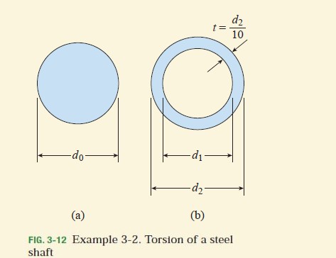
A steel shaft is to be manufactured either as a solid circular bar or as a circular tube (Fig. 3-12). The shaft is required to transmit a torque of 1200 N⋅m without exceeding an allowable shear stress of 40 MPa nor an allowable rate of twist of 0.75°/m. (The shear modulus of elasticity of the steel is 78 GPa.)
(a) Determine the required diameter d_{0} of the solid shaft.
(b) Determine the required outer diameter d_{2} of the hollow shaft if the thickness t of the shaft is specified as one-tenth of the outer diameter.
(c) Determine the ratio of diameters (that is, the ratio d_{2}/ d_{0}) and the ratio of weights of the hollow and solid shafts.
Learn more on how we answer questions.
(a) Solid shaft. The required diameter d_{0} is determined either from the allowable shear stress or from the allowable rate of twist. In the case of the allowable shear stress we rearrange Eq. (3-12) and obtain
\tau _{max}=\frac{16T}{\pi d^{3} } (3-12)
d^{3}_{0}=\frac{16T}{\pi \tau _{allow} } =\frac{16\left(1200 N⋅m\right) }{\pi \left(40 MPa\right) }=152.8\times 10^{-6} m^{3}from which we get
d_{0}=0.0535 m=53.5 mm
In the case of the allowable rate of twist, we start by finding the required polar moment of inertia (see Eq. 3-14):
\theta =\frac{T}{GI_{P} } (3-14)
I_{P} =\frac{T}{G\theta _{allow} } =\frac{1200 N⋅m}{\left(78 GPa\right)\left(0.75^{°}/m \right) \left(\pi rad/180^{°} \right) }=1175\times 10^{-9} m^{4}Since the polar moment of inertia is equal to \pi d^{4} /32, the required diameter is
d^{4}_{0}=\frac{32I_{P} }{\pi }=\frac{32\left(1175\times 10^{-9} m^{4} \right) }{\pi }=11.97\times 10^{-6} m^{4}or
d_{0} =0.0588 m=58.8 mm
Comparing the two values of d_{0}, we see that the rate of twist governs the design and the required diameter of the solid shaft is
d_{0}=58.8 mm
In a practical design, we would select a diameter slightly larger than the calculated value of d_{0}; for instance, 60 mm.
(b) Hollow shaft. Again, the required diameter is based upon either the allowable shear stress or the allowable rate of twist. We begin by noting that the outer diameter of the bar is d_{2} and the inner diameter is
d_{1}=d_{2} – 2t=d_{2} – 2\left(0.1d_{2} \right)=0.8d_{2}Thus, the polar moment of inertia (Eq. 3-16) is
I_{P} =\frac{\pi }{2}\left(r^{4} _{2} -r^{4}_{1} \right)=\frac{\pi }{32}\left(d^{4}_{2} -d^{4}_{1} \right) (3-16)
I_{P}=\frac{\pi }{32}\left(d^{4}_{2} – d^{4}_{1} \right)=\frac{\pi }{32}\left[d^{4}_{2} – \left(0.8d_{2} \right)^{4} \right] =\frac{\pi }{32} \left(0.5904d^{4} _{2} \right)=0.05796d^{4}_{2}In the case of the allowable shear stress, we use the torsion formula (Eq. 3-11) as follows:
\tau _{max} =\frac{Tr}{I_{P} } (3-11)
\tau _{allow}=\frac{Tr}{I_{P} }=\frac{T\left(d_{2}/2 \right) }{0.05796d^{4}_{2} } =\frac{T}{0.1159d^{3}_{2} }Rearranging, we get
d^{3}_{2}=\frac{T}{0.1159 \tau_{allow} }=\frac{1200 N⋅m}{0.1159\left(40 MPa\right) }=258.8\times 10^{-6} m^{3}Solving for d_{2} gives
d_{2} =0.0637 m=63.7 mm
which is the required outer diameter based upon the shear stress.
In the case of the allowable rate of twist, we use Eq. (3-14) with θ replaced by \theta _{allow} and I_{P} replaced by the previously obtained expression; thus,
\theta _{allow}=\frac{T}{G\left(0.05796d^{4}_{2} \right) }from which
d^{4} _{2} =\frac{T}{0.05796G\theta _{allow} }=\frac{1200 N⋅m} {0.05796\left(78 GPa\right)\left(0.75^{\circ}/m\right)\left(\pi rad/180^{\circ}\right)} =20.28\times 10^{-6} m^{4}
Solving for d_{2} gives
d_{2} =0.0671 m=67.1 mm
which is the required diameter based upon the rate of twist.
Comparing the two values of d_{2}, we see that the rate of twist governs the design and the required outer diameter of the hollow shaft is
d_{2} =67.1 mm
The inner diameter d_{1} is equal to 0.8 d_{2}, or 53.7 mm. (As practical values, we might select d_{2} = 70 mm and d_{1}= 0.8 d_{2} = 56 mm.)
(c) Ratios of diameters and weights. The ratio of the outer diameter of the hollow shaft to the diameter of the solid shaft (using the calculated values) is
\frac{d_{2} }{d_{0} }=\frac{67.1 mm}{58.8 mm}=1.14Since the weights of the shafts are proportional to their cross-sectional areas, we can express the ratio of the weight of the hollow shaft to the weight of the solid shaft as follows:
\frac{W_{hollow} }{W_{solid} }=\frac{A_{hollow} }{A_{solid} }=\frac{\pi \left(d^{2}_{2}-d^{2}_{1} \right)/4 }{\pi d^{2}_{0} /4 }=\frac{d^{2}_{2}-d^{2}_{1} }{d^{2}_{0} } =\frac{\left(67.1 mm\right)^{2}-\left(53.7 mm\right) ^{2} }{\left(58.8 mm\right)^{2} } =0.47These results show that the hollow shaft uses only 47% as much material as does the solid shaft, while its outer diameter is only 14% larger.
Note: This example illustrates how to determine the required sizes of both solid bars and circular tubes when allowable stresses and allowable rates of twist are known. It also illustrates the fact that circular tubes are more efficient in the use of materials than are solid circular bars.