Question 5.17: A tubular beam ACB of length L = 60 in. is pin-supported at ...
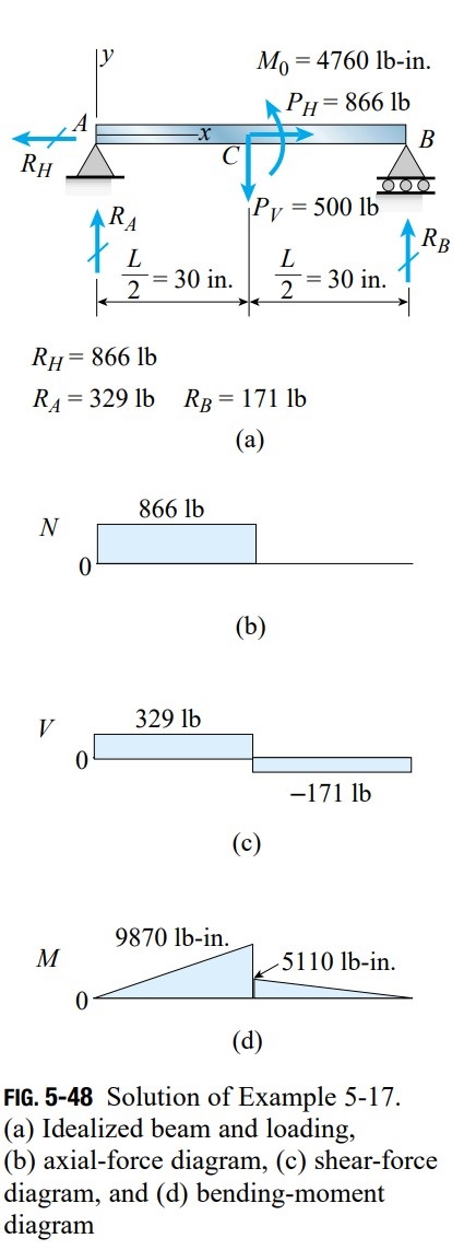
A tubular beam ACB of length L = 60 in. is pin-supported at its ends and loaded by an inclined force P at midlength (Fig. 5-47a). The distance from the point of application of the load P to the longitudinal axis of the tube is d = 5.5 in. The cross section of the tube is square (Fig. 5-47b) with outer dimension b = 6.0 in., area A = 20.0 in.², and moment of inertia I = 86.67 in.^{4}
Determine the maximum tensile and compressive stresses in the beam due to a load P = 1000 lb.
Learn more on how we answer questions.
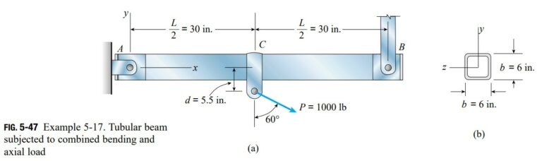
Beam and loading. We begin by representing the beam and its load in idealized form for purposes of analysis (Fig. 5-48a). Since the support at end A resists both horizontal and vertical displacement, it is represented as a pin support. The support at B prevents vertical displacement but offers no resistance to horizontal displacement, so it is shown as a roller support.
The inclined load P is resolved into horizontal and vertical components P_{H} and P_{V}, respectively:
The horizontal component P_{H} is shifted to the axis of the beam by the addition of a moment M_{0} (Fig. 5-48a):
M_0=P_H d=(866.0 lb )(5.5 \text { in.})=4760 lb -\text {in.}Note that the loads P_{H}, P_{V}, and M_{0} acting at the midpoint C of the beam are statically equivalent to the original load P.
Reactions and stress resultants. The reactions of the beam (R_{H}, R_{A}, and R_{B}) are shown in Fig. 5-48a. Also, the diagrams of axial force N, shear force V, and bending moment M are shown in Figs. 5-48b, c, and d, respectively. All of these quantities are found from free-body diagrams and equations of equilibrium, using the techniques described in Chapter 4.
Stresses in the beam. The maximum tensile stress in the beam occurs at the bottom of the beam (y = -3.0 in.) just to the left of the midpoint C. We arrive at this conclusion by noting that at this point in the beam the tensile stress due to the axial force adds to the tensile stress produced by the largest bending moment. Thus, from Eq. (5-53), we get
= 43 psi + 342 psi = 385 psi
The maximum compressive stress occurs either at the top of the beam (y = 3.0 in.) to the left of point C or at the top of the beam to the right of point C. These two stresses are calculated as follows:
\left(\sigma_c\right)_{ left }=\frac{N}{A}-\frac{M y}{I}=\frac{866 \text {lb}}{20.0 \text { in.}^2}-\frac{(9870 \text {lb-in.})(3.0 \text {in.})}{86.67 \text {in.}^4}
= 43 psi – 342 psi = -299 psi
\left(\sigma_c\right)_{\text {right }}=\frac{N}{A}-\frac{M y}{I}=0-\frac{(5110 \text {lb-in.})(3.0 \text {in.})}{86.67 \text {in.}^4}=-177 psi
Thus, the maximum compressive stress is
\left(\sigma_c\right)_{\max }=-299 psiand occurs at the top of the beam to the left of point C.
Note: This example shows how the normal stresses in a beam due to combined bending and axial load can be determined. The shear stresses acting on cross sections of the beam (due to the shear forces V) can be determined independently of the normal stresses, as described earlier in this chapter. Later, in Chapter 7, we will see how to determine the stresses on inclined planes when we know both the normal and shear stresses acting on cross-sectional planes.