Question 4.CS.1B: Bicycle Brake Lever Stress and Deflection Analysis Problem D...
Bicycle Brake Lever Stress and Deflection Analysis
Problem Determine the stresses and deflections at critical points in the brake lever shown in Figures 3-1 (repeated here) and 4-47.
Given The geometry and loading are known from Case Study 1A (p. 79). The pivot pin is 8-mm dia. The average human’s hand can develop a grip force of about 267 N (60 lb) in the lever position shown.
Assumptions The most likely failure points are the two holes where the pins insert and at the root of the cantilever-beam lever handle. The cross section of the lever handle is essentially circular.


Learn more on how we answer questions.
See Figures 4-47 to 4-48.
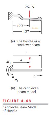
1 The 14.3-mm-diameter portion of the handle can be modeled as a cantilever beam with an intermediate concentrated load as shown in Figure 4-48 if we assume that the more massive block at its left end serves as a “ground plane.” The location of likely failure is the root of the round-handle portion where the shear and moment are both maximum, as shown in Figure 4-24 (p. 168) for this model that was analyzed for reactions, moments, and deflections in Examples 3-3A , 3-3B and 4-5. From \Sigma F=0 \text { and } \Sigma M=0 , we find that R_{1} = 267 N and M_{1} = 20.34 N-m. The tensile bending stress at the root of the cantilever is maximum at the outer fiber (at point P as shown in Figure 4-47) and is found from equation 4.11b:
\sigma_x=\frac{M c}{I}=\frac{(F \cdot a) c}{I}=\frac{(267 N \cdot 0.0762 m )\left\lgroup \frac{0.0143}{2}\right\rgroup m }{\frac{\pi(0.0143)^4}{64} m ^4}=70.9 MPa (a)
This is a relatively low stress for this material. There is some stress concentration due to the small radius at the root of the beam but since this is made of a marginally ductile cast material (5% elongation to fracture) we can ignore the stress concentrations on the basis that local yielding will relieve them.
2 The effective length-to-depth ratio of this beam is small at 76.2 / 14.3 = 5.3. Since this ratio is less than 10, the shear stress due to transverse loading will be calculated. For this solid-circular section, it is found from equation 4.15c (p. 161) to be:
\tau_{\max }=\frac{4}{3} \frac{V}{A} (4.15c)
\tau_{x y}=\frac{4 V}{3 A}=\frac{4(267) N }{\frac{3 \pi(14.3)^2}{4} mm ^2}=2.22 MPa (b)
The shear stress is maximum at the neutral axis (point Q) and the normal bending stress is maximum at the outer fiber (point P). The largest principal stress (equation 4.6, p. 145) at the top outer fiber is then \sigma_1=\sigma_x=70.9 MPa , \sigma_2=\sigma_3=0, \text { and } \tau_{\max }=35.45 MPa . The Mohr circle for this stress element looks like the one in Figure 4-8 (repeated overleaf for convenience).
\begin{aligned} \sigma_a, \sigma_b &=\frac{\sigma_x+\sigma_y}{2} \pm \sqrt{\left\lgroup \frac{\sigma_x-\sigma_y}{2} \right\rgroup ^2+\tau_{x y}^2} \\ \sigma_c &=0 \end{aligned} (4.6a)
\tau_{\max }=\tau_{13}=\frac{\left|\sigma_1-\sigma_3\right|}{2} (4.6b)
3 The deflection calculation for the handle is complicated by its curved geometry and its slight taper from root to end. A first approximation of the deflection can be obtained by simplifying the model to a straight beam of constant cross section as shown in Figure 4-48b. The deflection due to transverse shear will also be neglected. This will be in slight error in a nonconservative direction but will nevertheless give an order-ofmagnitude indication of the deflection. If this result shows a problem with excessive deflection, it will be necessary to improve the model. Equation (i) from Example 4-5 provides the deflection equation for our simple model. In this case, l = 127 mm, a = 76.2 mm, and x=l for the maximum deflection at the end of the beam.
\begin{aligned} y &=\frac{F}{6 E I}\left[x^3-3 a x^2-\langle x-a\rangle^3\right] \\ &=\frac{267}{6(71.7 E 3)(2.04 E 3)}\left[127^3-3(76.2) 127^2-(127-76.2)^3\right] \\ &=-0.54 mm \end{aligned} (c)
This is about a 0.02-in deflection at the handle-end, which is not considered excessive in this application. See Figure 4-24 (p. 168) for a plot of the general shape of this beam’s deflection curve, though the values are different in that example.
4 Other locations of likely failure must also be checked. The material around the two holes may experience any of several modes of failure due to bearing stress, direct shear stress, or tearout. The hole at point A in Figure 4-47 contains a pivot pin which bears against the handle with the 1 951-N force shown. We will check this for the three modes listed above.
5 Bearing stress is compressive and is considered to act upon the projected area of the hole, which, in this case, is the 8-mm hole diameter times the total length of the bearing (two 6.4-mm-thick flanges).
\begin{array}{l} A_{\text {bearing }}=\text { dia } \cdot \text { thickness }=8(2)(6.4)=102.4 mm ^2 \\ \sigma_{\text {bearing }}=\frac{F_{12}}{A_{\text {bearing }}}=\frac{1951 N }{102.4 mm ^2}=19.1 MPa \end{array} (d)
6 Tearout in this case requires that (4) 6.4-mm-thick sections fail in shear through the 5-mm length of material between hole and edge. (See also Figure 4-13, p. 155, for a definition of tearout area.)
\begin{array}{l} A_{\text {tearout }}=\text { length } \cdot \text { thickness }=7.1(4)(6.4)=181.8 mm ^2 \\ \tau_{\text {tearout }}=\frac{F_{12}}{A_{\text {tearout }}}=\frac{1951 N }{181.8 mm ^2}=10.7 MPa \end{array} (e)
7 These are very low stresses for the specified material but remember that the applied force used is based on typical human-hand force capability and does not anticipate abuse due to impact or other means.
8 The cable-end inserts in a blind hole, which is half-slotted to allow the cable to pass through at assembly as shown in Figure 4-47. This slot weakens the part and makes the section at C the most likely failure location at this joint. We will assume that failure of the open (slotted) half of the material around the hole is sufficient to disable the part, since the cable-end could then slip out. The small section that retains the cable pin can be modeled to a first approximation as a cantilever beam with a cross-sectional width of (25 – 5) / 2 = 10 mm and a depth of 5 mm. This is a conservative assumption, as it ignores the increase in depth due to the radius of the hole. The moment arm of the force will be assumed to be equal to the radius of the pin or 4 mm. The force on the slotted half of the width is taken as half of the total force of 1 914 N on the cable. The bending stress at the outer fiber at point C is then
\sigma_x=\frac{M c}{I}=\frac{\frac{1914}{2}\ \left\lgroup \frac{5}{2} \right\rgroup(4)}{\frac{10(5)^3}{12}}=91.9 MPa (f)
and the shear due to transverse loading at the neutral axis is (Eq. 4.14b, p. 161)
\tau_{x y}=\frac{3 V}{2 A}=\frac{3(957)}{2(10)(5)}=28.7 MPa (g)
9 The normal stress is principal here, as shown in Figure 4-8 (p. 152), and the maximum shear stress is then half of the principal normal stress. These are the highest stresses found for the three sections checked. A failure analysis of this part will be done in the continuation of this case study in the next chapter.
10 This preliminary analysis shows some of the areas that might benefit from further investigation. A more complete stress analysis of this case study is done in Chapter 8 using Finite Element Analysis (FEA). You may examine the model for this case study by opening the file CASE1B in the program of your choice.