Question 8.7: Design a coupled line bandpass filter with N = 3 and a 0.5 d...
Design a coupled line bandpass filter with N = 3 and a 0.5 dB equal-ripple re-sponse. The center frequency is 2.0 GHz, the bandwidth is 10%, and Z_{0} = 50 Ω.
What is the attenuation at 1.8 GHz?
Learn more on how we answer questions.
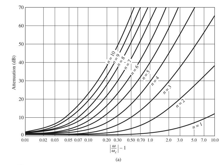
The fractional bandwidth is Δ = 0.1. We can use Figure 8.27a to obtain the at-tenuation at 1.8 GHz, but first we must use (8.71) to convert this frequency to the normalized low-pass form (ω_{c} = 1):
\omega \leftarrow \frac{1}{\Delta }(\frac{\omega }{\omega _{0}}-\frac{\omega _{0}}{\omega } ) =\frac{1}{0.1}(\frac{1.8}{2.0}-\frac{2.0}{1.8} )=-2.11.Then the value on the horizontal scale of Figure 8.27a is
\left|\frac{\omega }{\omega _{c}} \right| -1 = \left|-2.11\right| -1 =1.11,which indicates an attenuation of about 20 dB for N = 3.
The low-pass prototype values, gn, are given in Table 8.4; then (8.121) can
be used to calculate the admittance inverter constants, J_{n}. Finally, the even- and odd-mode characteristic impedances can be found from (8.108). These results are summarized in the following table:
|
n |
g_{n} |
Z_{0}j_{n} |
Z_{0e}(Ω) |
Z_{0o}(Ω) |
|
1 |
1.5963 |
0.3137 |
70.61 |
39.24 |
|
2 |
1.0967 |
0.1187 |
56.64 |
44.77 |
|
3 |
1.5963 |
0.1187 |
56.64 |
44.77 |
|
4 |
1.0000 |
0.3137 |
70.61 |
39.24 |
Note that the filter sections are symmetric about the midpoint. The calculated response of this filter is shown in Figure 8.46; passbands also occur at 6 GHz, 10 GHz, etc.