See Figure 4-29 and Table 4-3.
1 Equations 4.26 will apply for all sections, provided that we substitute J for K and J/r for Q in the case of the closed-circular section.
\tau_{\max }=\frac{T}{Q} (4.26a)
\theta=\frac{T l}{K G} (4.26b)
2 The unformed flat plate behaves as a solid rectangular section as shown in Figure 4-29a and Table 4-3. It has dimensions a = w / 2 = 0.05 m and b = t / 2 = 0.000 5 m:
\begin{aligned} K &=a b^3\left[\frac{16}{3}-3.36 \frac{b}{a}\left\lgroup1-\frac{b^4}{12 a^4}\right\rgroup \right] \\ &=(0.05)(0.0005)^3\left[5.333-3.36 \frac{0.0005}{0.05}\left\lgroup1-\frac{(0.0005)^4}{12(0.05)^4}\right\rgroup \right] \\ K &=3.312 E-11 m ^4=33.123 mm ^4 \\ \theta &=\frac{T l}{G K}=\frac{(10)(1)}{(8.08 E 10)(3.312 E-11)}=3.736 rad =214.1^{\circ} \end{aligned} (a)
This is obviously a rather large angular deflection, indicating that the flat plate has been wound into a corkscrew by this torsional load.
\begin{aligned} Q &=\frac{8 a^2 b^2}{3 a+1.8 b} \\ &=\frac{8(0.05)^2(0.0005)^3}{3(0.05)+1.8(0.0005)} \\ Q &=3.313 E-8 m ^3=33.13 mm ^3 \\ \tau &=\frac{T}{Q}=\frac{10}{3.313 E-8}=301.8 MPa =43772 psi \end{aligned} (b)
The maximum shear stress is 300 MPa, which would require a material with a tensile yield strength of over 520 MPa (75 000 psi) in order not to yield and take a set. This requires a high-strength steel. (See Section 5.1 for discussion of this relationship between tensile and shear strength as defined in equation 5.9b. on p. 251.)
S_{y s}=0.577 S_y (5.9b)
3 The open-circular shape is now formed into a 3.18-cm diameter tube, but its longitudinal seam is left unwelded and open as shown in Figure 4-29b. The expressions for K and Q from Table 4-3 are
\begin{aligned} K &=\frac{2}{3} \pi r t^3 \\ &=\frac{2}{3} \pi \frac{\left(\frac{w}{\pi}-t\right)}{2} t^3=\frac{1}{3}(w-\pi t) t^3=\frac{1}{3}(0.1-0.001 \pi) 0.001^3 \\ K &=3.2286 E-11 m ^4=32.286 mm ^4 \\ \theta &=\frac{T l}{G K}=\frac{(10)(1)}{(8.08 E 10)(3.2286 E-11)}=3.833 rad =219.6^{\circ} \end{aligned} (c)
This is as large an angular deflection as that of the flat plate.
\begin{aligned} Q &=\frac{4 \pi^2 r^2 t^2}{6 \pi r+1.8 t} \\ &=\frac{4 \pi^2(0.01542)^2(0.001)^3}{6 \pi(0.01542)+1.8(0.001)} \\ Q &=3.209 E-8 m ^3=32.09 mm ^3 \\ \tau &=\frac{T}{Q}=\frac{10}{3.209 E-8}=311.6 MPa =45201 psi \end{aligned} (d)
The stress and deflection are unacceptable. It is just as bad a design as the flat plate.
4 The closed-square tube is formed by folding the sheet into a square section with side dimension s = a = w / 4. The seam is welded as shown in Figure 4-29c. From Table 4-3, K and Q, and the stress and deflection are now
\begin{array}{l} K=\frac{2 t^2(a-t)^4}{2 a t-2 t^2}=\frac{2 t^2\left\lgroup\frac{w}{4}-t\right\rgroup^4}{2 \frac{w}{4} t-2 t^2}=\frac{2(0.001)^2\left\lgroup\frac{0.1}{4}-0.001\right\rgroup^4}{2\left\lgroup\frac{0.1}{4}\right\rgroup(0.001)-2(0.001)^2} \\ K=1.382 E-8 m ^4=13824 mm ^4 \\ \theta=\frac{T l}{G K}=\frac{(10)(1)}{(8.08 E 10)(1.382 E-8)}=0.00895 rad =0.51^{\circ} \end{array} (e)
\begin{array}{l} Q=2 t(a-t)^2=2 t\left\lgroup\frac{w}{4}-t\right\rgroup ^2=2(0.001)\left\lgroup\frac{0.1}{4}-0.001\right\rgroup ^2 \\ Q=1.152 E-6 m ^3 \\ \tau=\frac{T}{Q}=\frac{10}{1.152 E-6}=8.7 MPa =1259 psi \end{array} (f)
This angular deflection of the square tube is much less than that of either open section, and the maximum shear stress is now much more reasonable.
5 The closed-circular shape is formed into a 3.18-cm outside diameter tube and its longitudinal seam is welded shut as shown in Figure 4-29d. We can either use equations 4.24 and 4.25 (p. 178) or use the general equations 4.26 (p. 178) involving K and Q, which are now a function of J for this circular shape. For the deflection,
\theta=\frac{T l}{J G} (4.24)
J=\frac{\pi d^4}{32} (4.25a)
J=\frac{\pi\left(d_o^4-d_i^4\right)}{32} (4.25b)
\begin{aligned} K &=J=\frac{\pi\left\lgroup d_o^4-d_i^4\right\rgroup }{32} ; \quad d_o=\frac{w}{\pi}, \quad d_i=d_o-2 t \\ &=\frac{\pi\left[\left\lgroup \frac{w}{\pi} \right\rgroup ^4-\left\lgroup \frac{w}{\pi}-2 t\right\rgroup ^4\right]}{32}=\frac{\pi\left[\left\lgroup \frac{0.1}{\pi}\right\rgroup ^4-\left\lgroup\frac{0.1}{\pi}-2\{0.001\}\right\rgroup ^4\right]}{32} \\ K &=J=2.304 E-8 m ^4=23041 mm ^4 \\ \theta &=\frac{T l}{G K}=\frac{(10)(1)}{(8.08 E 10)(2.304 E-8)}=0.0054 rad =0.31^{\circ} \end{aligned} (g)
and for the maximum shear stress at the outer surface,
\begin{aligned} Q=\frac{J}{r}=\frac{\pi\left\lgroup d_o^4-d_i^4\right\rgroup }{32 r_o} &=\frac{\pi\left[\left\lgroup\frac{w}{\pi}\right\rgroup ^4-\left\lgroup\frac{w}{\pi}-2 t\right\rgroup ^4\right]}{32\left\lgroup\frac{w}{2 \pi}\right\rgroup }=\frac{\pi\left[\left\lgroup\frac{0.1}{\pi}\right\rgroup ^4-\left\lgroup\frac{0.1}{\pi}-2\{0.001\}\right\rgroup ^4\right]}{32\left\lgroup\frac{0.1}{2 \pi}\right\rgroup } \\ Q &=1.448 E-6 m ^3 \\ \tau &=\frac{T}{Q}=\frac{10}{1.448 E-6}=6.91 MPa =1002 psi \end{aligned} (h)
6 This closed circular design has the smallest stress and deflection and is clearly the best choice of the four designs presented. The wall thickness could be increased to further reduce stress and deflection if desired. The design needs to be checked for possible torsional buckling as well. The files EX04-09 can be opened in the program of your choice if desired.
| Table 4-3 Expressions for K and Q for Some Cross-Section Shapes in Torsion The Black Dots Indicate Points of Maximum Shear Stress (Source: Ref. 4 with Permission) |
||
| Shape | K | Q |
| solid square
|
K=2.25 a^4 | Q=\frac{a^3}{0.6} |
| hollow square
|
K=\frac{2 t^2(a-t)^4}{2 a t-2 t^2} | Q=2 t(a-t)^2 |
| inside corners may have higher stress if corner radius is small | ||
| solid rectangle
|
K=a b^3\left[\frac{16}{3}-3.36 \frac{b}{a}\left\lgroup1-\frac{b^4}{12 a^4}\right\rgroup \right] | Q=\frac{8 a^2 b^2}{3 a+1.8 b} |
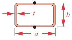
| hollow rectangle
|
K=\frac{2 t^2(a-t)^2(b-t)^2}{a t+b t-2 t^2} | Q=2 t(a-t)(b-t) |
| inside corners may have higher stress if corner radius is small | ||
| solid ellipse
|
K=\frac{\pi a^3 b^3}{a^2+b^2} | Q=\frac{\pi a b^2}{2} |
| hollow ellipse
|
K=\frac{\pi a^3 b^3}{a^2+b^2}\left[1-\left\lgroup1-\frac{t}{a}\right\rgroup ^4\right] | Q=\frac{\pi a b^2}{2}\left[1-\left\lgroup1-\frac{t}{a}\right\rgroup ^4\right] |
| open circular tube
|
K=\frac{2}{3} \pi r t^3 ; \quad t \ll r | Q=\frac{4 \pi^2 r^2 t^2}{6 \pi r+1.8 t} ; \quad t \ll r |
open arbitrary shape U = length of median line |
K=\frac{1}{3} U t^3 ; \quad t \ll U | Q=\frac{U^2 t^2}{3 U+1.8 t} ; \quad t \ll U |
| t must be much smaller than minimum radius of curvature | ||