Question 11.3: Evaluate the significance of interfacial shear for the condi...
Evaluate the significance of interfacial shear for the conditions of Example 11.2 and the following specifications:
(a) For the vertical condenser, the vapor flows downward through the tubes.
(b) For the horizontal shell-side condenser, the unit consists of an E-shell with an ID of 12 in. The condenser has 20% cut segmental baffles with a spacing of 4.8 in., and a triangular tube layout with a pitch of 1.0 in.
Learn more on how we answer questions.
(a) The following data are obtained from Example 11.2, part (a):
| T_{V}=T_{\text {sat }}=207^{\circ} F | \mu_{ L }=0.73 cp |
| T_{f} \cong 169^{\circ} F | \operatorname{Pr}_{L}=13.4 |
| T_{ W } \cong 156^{\circ} F | D_{i}=0.584 in. |
| P_{\text {sat }} \cong 1 atm =14.7 psia | L = 12 ft |
| k_{L}=0.095 Btu / h \cdot ft \cdot{ }^{\circ} F | n_{t}=109 |
| \rho_{L}=49 lbm / ft ^{3} |
Additional data needed for the calculations are:
Molecular weight of propyl alcohol = 60
\mu_{w}=0.85 cp \text { at } T_{w}=156^{\circ} Ffrom Figure A.1
\rho_{V}=\frac{P M}{\tilde{R} T}=\frac{14.7 \times 60}{10.73(207 + 460)}=0.123 lbm / ft ^{3}
The shear-controlled heat-transfer coefficient is given by Equation (11.55), which involves the coefficient, h_{LO}, for the total flow (5000 lb/h) as liquid. The Reynolds number is calculated first:
h = h_{LO} [1 + x(\rho_{L} – \rho_{V})/\rho_{V}]^{0.5} (11.55)
R e_{L O}=\frac{4 \dot{m} / n_{t}}{\pi D_{i} \mu_{L}}=\frac{4 \times 5000 / 109}{\pi(0.584 / 12) \times 0.73 \times 2.419}=679.6
Since the total condensate flow is laminar, the Boyko–Kruzhilin correlation is not strictly applicable. However, a conservative estimate for the shear-controlled coefficient can be obtained by using Equation (11.55) along with a laminar-flow correlation to calculate h_{LO}. (See Problem 11.2 for an alternative approach.) Hence, Equation (2.36) is used as follows:
T_{w,ave} = \frac{T_{w1} + T_{w2}}{2} (2.36)
N u_{L O}=1.86\left(\operatorname{Re}_{L O} Pr_{L} D_{i} / L\right)^{1 / 3}\left(\mu_{L} / \mu_{w}\right)^{0.14}
=1.86[679.6 \times 13.4(0.584 / 12) / 12]^{1 / 3}(0.73 / 0.85)^{0.14}
N u_{L O}=6.06
h_{L O}=6.06 \times k_{L} / D_{i}=6.06 \times 0.095 /(0.584 / 12)=11.8 Btu / h \cdot ft ^{2} \cdot{ }^{\circ} F
At the condenser inlet, the vapor fraction is x_{\text {in }} = 1.0. Hence, from Equation (11.55):
h_{\text {in }}=h_{L O}\left[1 + x_{i n}\left(\rho_{L}-\rho_{V}\right) / \rho_{V}\right]^{0.5}
=11.8[1 + 1.0(49 – 0.123) / 0.123]^{0.5}
h_{\text {in }}=236 Btu / h \cdot ft ^{2} \cdot{ }^{\circ} F
At the condenser outlet the vapor fraction is zero, and therefore:
h_{\text {out }}=h_{L O}=11.8 Btu / h \cdot ft ^{2} \cdot{ }^{\circ} F
The average heat-transfer coefficient for shear-controlled condensation is the arithmetic average of the inlet and outlet values:
h_{ sh }=0.5\left(h_{ in }+h_{o u t}\right)=0.5(236+11.8)=124 Btu / h \cdot ft ^{2} \cdot{ }^{\circ} F
This result is the same order of magnitude as the average coefficient for gravity-controlled condensation (147 Btu/h · ft²·º F) calculated in Example 11.2, part (a). Therefore, both gravity and interfacial shear effects are significant, and Equation (11.54) can be used to estimate the resultant heat-transfer coefficient
h=\left(h_{s h}^{2}+h_{g r}^{2}\right)^{1 / 2}=\left[(124)^{2}+(147)^{2}\right]^{1 / 2}=192 Btu / h \cdot ft ^{2} \cdot{ }^{\circ} F
This value is about 30% higher than the result based on gravity-controlled condensation alone. Comparison with other methods (see Problems 11.1 and 11.2 for two examples) indicates that the calculated value of h is, in fact, somewhat conservative.
(b) The following data are obtained from Example 11.2, part (b):
| T_{f}=193^{\circ} F | T_{w} \cong 188^{\circ} F | \mu_{ L }=0.58 cp |
Additional data needed for the calculations are:
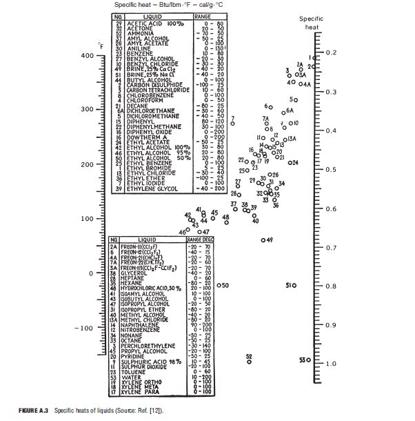
| C_{P, L}=0.75 Btu / lbm \cdot{ }^{\circ} F | from Figure A.3 |
| \mu_{V}=0.0095 cp | from Figure A.2 |
| \mu_{w}=0.60 cp \text { at } T_{w}=188^{\circ} F | from Figure A.1 |
Pr_{L}=\frac{C_{P, L} \mu_{L}}{k_{L}}=\frac{0.75 \times 0.58 \times 2.419}{0.095} \cong 11.1
Other data are the same as in part (a).
The shear-controlled heat-transfer coefficient is given by Equation (11.56), which involves the coefficient, h_{ L }, for the liquid phase flowing alone. The Simplified Delaware method is used here to calculate h_{ L }. A vapor weight fraction of 0.9 is selected, giving a liquid flow rate of:
h/h_{L} = 1.26 X_{tt}^{- 0.78} (11.56)
\dot{m}_{ L }=(1-x) \dot{m}=0.1 \times 5000=500 lbm / h
The flow area through the tube bundle is:
a_{s}=\frac{d_{s} C^{\prime} B}{144 P_{T}}=\frac{12 \times 0.25 \times 4.8}{144 \times 1.0}=0.10 ft ^{2}
The mass flux is:
G_{L}=\dot{m}_{L} / a_{s}=500 / 0.10=5000 lbm / h \cdot ft ^{2}
From Figure 3.17, the equivalent diameter is D_{e} = 0.99/12 = 0.0825 ft. Thus, the Reynolds number is:
R e_{L}=\frac{D_{e} G_{L}}{\mu_{L}}=\frac{0.0825 \times 5000}{0.58 \times 2.419}=294.0
Next, the Colburn j-factor is calculated using Equation (3.21) with B / d_{s}=4.8 / 12 = 0.4
j_{H}=0.5\left(1+B / d_{s}\right)\left(0.08 R e_{L}^{0.6821}+0.7 R e_{L}^{0.1772}\right)
=0.5(1 + 0.4)\left\{0.08(294)^{0.6821} + 0.7(294)^{0.1772}\right\}
j_{H}=4.04
Equation (3.20) is used to calculate h_{ L }:
h_{L}=j_{H}\left(k_{L} / D_{e}\right) P r_{L}^{1 / 3}\left(\mu_{L} / \mu_{w}\right)^{0.14}
=4.04(0.095 / 0.0825)(11.1)^{1 / 3}(0.58 / 0.60)^{0.14}
h_{L}=10.3 Btu / h \cdot ft ^{2} \cdot{ }^{\circ} F
Next, the Lockhart–Martinelli parameter is computed from Equation (9.37):
X_{ tt }=\left(\frac{1 – x}{x}\right)^{0.9}\left(\rho_{V} / \rho_{L}\right)^{0.5}\left(\mu_{L} / \mu_{V}\right)^{0.1}
=\left(\frac{1 – 0.9}{0.9}\right)^{0.9}(0.123 / 49)^{0.5}(0.58 / 0.0095)^{0.1}
X_{ tt }=0.0105
Substituting the values of h_{ L } and X_{ tt } in Equation (11.56) gives the local coefficient for shear-controlled condensation:
h_{s h}=1.26 X_{t t}^{-0.78} h_{L}=1.26(0.0105)^{-0.78} \times 10.3
h_{ sh }=454 Btu / h \cdot ft ^{2} \cdot{ }^{\circ} F
This value is about 44% higher than the value of 315 Btu/h · ft²·º F found for the average coefficient based on gravity-controlled condensation in Example 11.2. Thus, interfacial shear effects are significant at this point in the condenser.
Repeating the above calculations for vapor weight fractions of 0.5 and 0.1 yields the following results:
| x = 0.5 | x = 0.1 |
| \dot{m}_{ L }=2500 lbm / h | \dot{m}_{ L }=4500 lbm / h |
| G_{L}=25,000 lbm / h \cdot ft ^{2} | G_{L}=45,000 lbm / h \cdot ft ^{2} |
| R e_{L}=1470 | R e_{L}=2646 |
| j_{H}=9.89 | j_{H}=14.1 |
| h_{L}=25.3 Btu / h \cdot ft ^{2} \cdot{ }^{\circ}F | h_{L}=36.0 Btu / h \cdot ft ^{2} \cdot{ }^{\circ} F |
| X_{ tt }=0.076 | X_{ tt }=0.546 |
| h_{ sh }=238 Btu / h \cdot ft ^{2} \cdot{ }^{\circ} F | h_{ sh }=73 Btu / h \cdot ft ^{2} \cdot{ }^{\circ} F |
Interfacial shear effects are negligible at x = 0.1, but they are clearly significant over a large portion of the condensing range.