Question 3.1: Impact Loading on an Axial Rod Problem: The axial rod shown ...
Impact Loading on an Axial Rod
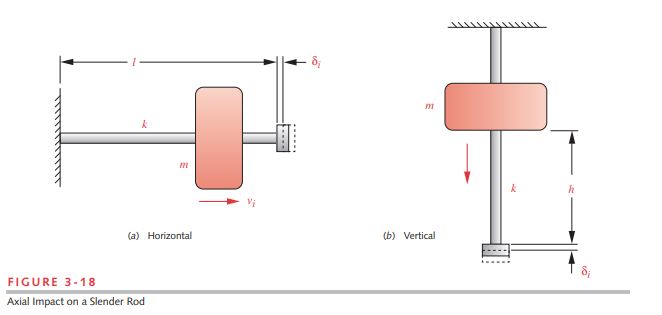
Problem: The axial rod shown in Figure 3-18a is hit by a mass moving at 1 m/sec.
a. Determine the sensitivity of the impact force to the length/diameter ratio of the rod for a constant 1-kg moving mass.
b. Determine the sensitivity of the impact force to the ratio of moving mass to rod mass for a constant length/diameter ratio of 10.
Given: The round rod is 100 mm long. The rod and moving mass are steel with E = 207 Gpa and a mass density of 7.86 g/cm³.
Assumptions: An approximate energy method will be acceptable. The correction factor for energy dissipation will be applied.
Learn more on how we answer questions.
See Figures 3-18a, 3-20, and 3-21.
1 Figure 3-18a shows the system. The moving mass strikes the flange on the end of the rod with the stated velocity of 1 m/sec.
2 For part (a), we will keep the moving mass constant at 1 kg, and the rod length constant at 100 mm and vary the rod diameter to obtain [altex]l/d[/latex] ratios in the range of 1 to 20. In the equations that follow we will show only one calculation made for the l/d ratio of 10. We can also compute all the values for a list of l/d ratios. The static deflection that would result from application of the weight force of the mass is calculated from the expression for the deflection of a bar in tension. (See equation 4.8 in the next chapter for the derivation.)
\Delta s=\frac{P l}{A E} (4.8)
\delta_{s t}=\frac{W l}{A E}=\frac{9.81 N (100 mm )}{78.54 mm ^2\left(2.07 E 5 N / mm ^2\right)}=0.06 \mu m (a)
The correction factor η is calculated here for an assumed mass ratio of 16.2,
\eta=\frac{1}{1+\frac{m_b}{3 m}}=\frac{1}{1+\frac{0.0617}{3(1)}}=0.98 (b)
These values (calculated for each different rod diameter d) are then substituted into equation 3.12 to find the force ratio F_{i} / W and the dynamic force F_{i }. For d = 10 mm
\frac{F_i}{W}=\frac{\delta_i}{\delta_{s t}}=v_i \sqrt{\frac{\eta}{g \delta_{s t}}} (3.12)
\begin{array}{l} \frac{F_i}{W}=v_i \sqrt{\frac{\eta}{g \delta_{s t}}}=1 \frac{ m }{ s } \sqrt{\frac{0.98}{9.81 \frac{ m }{ s ^2}(0.00006 m )}}=1285.9 \\ F_i=1285.9(9.81 N )=12612 N \end{array} (c)
The variation in force ratio with changes in l/d ratio for a constant amount of moving mass and a constant impact velocity (i.e., constant input energy) is shown in Figure 3-20. As the l/d ratio is reduced, the rod becomes much stiffer and generates much larger dynamic forces from the same impact energy. This clearly shows that impact forces can be reduced by increasing the compliance of the impacted system.
3 For part (b), we will keep the l/d ratio constant at 10 and vary the ratio between the moving mass and the rod mass over the range of 1 to 20. The files EX03-01B on the CD-ROM calculate all values for a range of mass ratios. The results for a mass ratio of 16.2 are the same as in part (a) above. Figure 3-21a shows that the dynamic force ratio F_{i} / W varies inversely with the mass ratio. However, the value of the dynamic force is increasing with mass ratio as shown in Figure 3-21b, because the static force W is also increasing with mass ratio.


