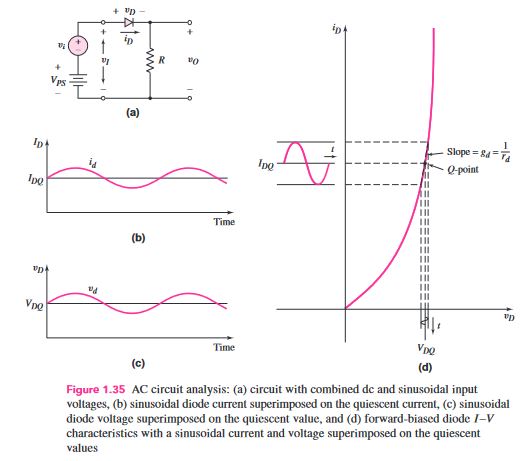
Question 1.11: Objective: Analyze the circuit shown in Figure 1.35(a). Assu...
Objective: Analyze the circuit shown in Figure 1.35(a). Assume circuit and diode parameters of V_{PS} = 5 V, R = 5 kΩ, V_{γ} = 0.6 V, and v_{i} = 0.1 sin ωt (V).
Learn more on how we answer questions.
Divide the analysis into two parts: the dc analysis and the ac analysis.
For the dc analysis, we set v_{i} = 0 and then determine the dc quiescent current from Figure 1.36(a) as
The dc value of the output voltage is
V_{o} = I_{DQ} R = (0.88) (5) = 4.4 VFor the ac analysis, we consider only the ac signals and parameters in the circuit in Figure 1.36(b). In other words, we effectively set V_{P S}=0. The ac Kirchhoff volt-age law (KVL) equation becomes
v_{i} = i_{d} r_{d} + i_{d} R = i_{d}(r_{d} + R)where r_{d} is again the small-signal diode diffusion resistance. From Equation (1.32), we have
r_{d} = \frac{1}{g_{d}} = \frac{V_{T}}{I_{DQ}} (1.32)
r_{d} = \frac{V_{T}}{I_{DQ}} = \frac{0.026}{0.88} = 0.0295 kΩThe ac diode current is
i_{d} = \frac{v_{i}}{r_{d} + R} = \frac{0.1 sin \omega t}{0.0295 + 5} ⇒ 19.9 sin \omega t (\mu A)The ac component of the output voltage is
v_{o} = i_{d} R = 0.0995 sin \omega t (V)Comment: Throughout the text, we will divide the circuit analysis into a dc analysis and an ac analysis. To do so, we will use separate equivalent circuit models for each analysis
