A curved beam has the shape shown in Figure 3–28 and is subjected to a pure bending moment of -640 lb . in. The inside radius is 2.90 in. Compute the maximum tensile and compressive stresses in the beam
Share
Share
Question 3.18: A curved beam has the shape shown in Figure 3–28 and is subj...

The Blue Check Mark means that this solution has been answered and checked by an expert. This guarantees that the final answer is accurate.
Learn more on how we answer questions.
Learn more on how we answer questions.
Objective: Compute the maximum tensile and compressive stresses.
Given: M = -640 lb . in that tends to decrease the radius of curvature.
r_i = 2.90 in (see Figure 3–28 for related dimensions).
Analysis: Apply Equations (3–28) and (3–29)
\sigma_{o}=\frac{M\left(R-r_{o}\right)}{A r_{o}\left(r_{c}-R\right)} (3.28)
\sigma_{i}=\frac{M\left(R-r_{i}\right)}{A r_{i}\left(r_{c}-R\right)} (3.29)
Results: Separate the shape into a composite of an inverted T-section 1 and a semicircular area 2. Compute cross-sectional area for each part:
\begin{aligned}&A_{1}=b_{1} f_{1}+b_{2} f_{2}=(0.80 \mathrm{in})(0.20 \mathrm{in})+(1.0\mathrm{in})(0.40 \mathrm{in}) \\&A_{1}=0.560 \mathrm{in}^{2} \\&A_{2}=\pi D^{2} /8=\pi(0.40 \mathrm{in})^{2} / 8=0.06283 \mathrm{in}^{2}\end{aligned}
Total area =A=A_{1}+A_{2}=0.560+0.06283=0.62283 \mathrm{in}^{2}
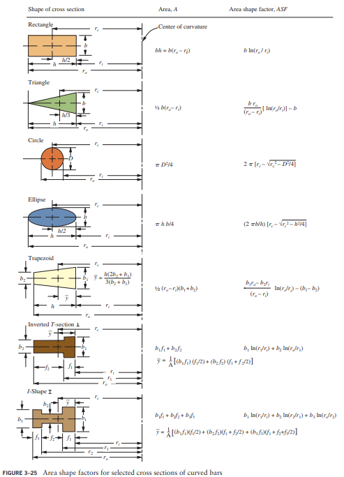
Now locate the centroid of each area with respect to the inside surface; from Figure 3-25:
\begin{aligned}&\bar{y}_{1}=\left[1 / A_{1}\right]\left[\left(b_{1} f_{1}\right)\left(f_{1} / 2\right)+\left(b_{2} f_{2}\right)\left(f_{1}+f_{2} / 2\right)\right] \\&\bar{y}_{1}=\left[1 / 0.56 \mathrm{in}^{2}\right][(0.80)(0.20)(0.10)+(1.0)(0.40)(0.70)]\mathrm{in}^{3} \\&\bar{y}_{1}=0.5286 \mathrm{in} \\&\bar{y}_{2}=1.20 \mathrm{in}+2\mathrm{D} / 3 \pi=1.20 \mathrm{in}+(2)(0.40 \mathrm{in}) /(3)(\pi) \\&\bar{y}_{2}=1.2849 \mathrm{in}\end{aligned}
Now locate the centroid of the composite area:
\begin{aligned}&\bar{y}_{c}=[1 / A]\left[A_{1} \bar{y}_{1}+A_{2} \bar{y}_{2}\right] \\&\bar{y}_{c}=\left[1 / 0.62283 \mathrm{in}^{2}\right][(0.560)(0.5286)+(0.06283)(1.2849)]\mathrm{in}^{3} \\&\bar{y}_{c}=0.60489 \mathrm{in}\end{aligned}
Now define the pertinent radii from the center of curvature:
\begin{aligned}&r_{o}=r_{i}+1.40 \text { in }=2.90 \text { in }+1.40 \text { in }=4.30\text { in } \\&r_{c}=r_{i}+\bar{y}_{c}=1.40 \text { in }+0.60489 \text { in }=3.5049 \text { in }\end{aligned}
Compute the value of the area shape factor, A S F_{\mathrm{i}}, for each part: For the T-shape:
\begin{aligned}&A S F_{1}=b_{1} \ln \left(r_{1} / r_{i}\right)+b_{2} \ln \left(r_{o 1} /r_{1}\right) \\&A S F_{1}=(0.80 \mathrm{in}) \ln (3.1 / 2.9)+(0.40 \mathrm{in}) \ln (4.1/3.1) \\&A S F_{1}=0.16519 \mathrm{in}\end{aligned}
For the semicircular area, we must determine the relationship between r_{i2} and D / 2 :
r_{i2}=4.10 \mathrm{in} at the base of the semicircle
D / 2=(0.40 \mathrm{in}) / 2=0.20 \mathrm{in}
Because r_{i2}>D / 2, we use the equation,
A S F_{2}=r_{i} \pi-D-\pi \sqrt{r_{i2}^{2}-D^{2} / 4}+2 \sqrt{r_{i2}^{2}-D^{2} / 4}\left[\sin ^{-1}\left(D / 2 r_{i}\right)\right]
[Note: Argument of inverse sine is in radians]
\begin{aligned}A S F_{2}=&(4.10) \pi-0.40-\pi \sqrt{(4.1)^{2}-(0.40)^{2} / 4} \\&+2\sqrt{(4.1)^{2}-(0.40)^{2} / 4}\left[\sin ^{-1}(0.40) /(2)(4.1)\right]=0.015016\mathrm{in}\end{aligned}
Compute the radius, R, from the center of curvature to the neutral axis from:
\begin{aligned}&R=A / \Sigma\left(A S F_{j}\right)=0.62283 \mathrm{in}^{2} /(0.16519+0.015016) \text { in } \\&R=3.4563 \text { in }\end{aligned}
Now compute:
\begin{aligned}r_{C}-R &=3.5049 \text { in }-3.4563 \text { in }=0.0486 \text { in }=e \\R-r_{o} &=3.4563 \text { in }-4.30 \text { in }=-0.8437 \text { in } \\R-r_{i} &=3.4563\text { in }-2.90 \text { in }=0.5563 \text { in }\end{aligned}
This locates the neutral axis from the inner surface.
Now compute the stress at outer surface, using Equation (3-28):
\begin{aligned}&\sigma_{o}=\frac{M\left(R-r_{o}\right)}{A r_{o}\left(r_{c}-R\right)}=\frac{(-640 \mathrm{lb} \cdot\mathrm{in})(-0.8437 \mathrm{in})}{\left(0.62283 \mathrm{in}^{2}\right)(4.30 \mathrm{in})(0.0486 \mathrm{in})} \\&\sigma_{o}=4149 \mathrm{lb} / \mathrm{in}^{2}=4149 \mathrm{psi}\end{aligned}
This is the maximum tensile stress in the bar.
Stress at inner surface, using Equation (3-29):
\begin{aligned}\sigma_{i} &=\frac{M\left(R-r_{j}\right)}{A r_{i}\left(r_{c}-R\right)}=\frac{(-640 \mathrm{lb} \cdot\mathrm{in})(0.5563 \mathrm{in})}{\left(0.62283 \mathrm{in}^{2}\right)(2.90 \mathrm{in})(0.0486 \mathrm{in})} \\\sigma_{\mathrm{i}}=-4056 \mathrm{lb} / \mathrm{in}^{2} &=-4056 \mathrm{psi}\end{aligned}
This is the maximum compressive stress in the bar.
Comment: This problem demonstrated the process for analyzing a composite section. Note that the maximum tensile and compressive stresses are very nearly equal for this design, a desirable condition for homogeneous, isotropic materials.

Related Answered Questions
Objective: Compute the relative deflection between...
Objective:
Compute the required section modulus [l...
Objective: Draw the free-body diagram of the shaft...
Objective: Determine the maximum tensile and compr...
Objective: Compute the maximum stress in the stepp...
Objective: Specify w, h, and t and ...
Objective: Compute the maximum tensile and compres...
Objective: Compute the torsional shear stress in t...
Objective:
Compute the angle of twist in the shaft...
Objective:
Compute the maximum shear stress and th...