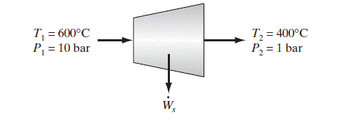
(This is another problem in which there is only a single thermodynamic unknown, the rate at which work is obtained, so we can expect to be able to solve this problem.)
The first step in solving any energy flow problem is to choose the thermodynamic system; the second step is to write the balance equations for the system. Here we take the turbine and its contents to be the system. The mass and energy balance equations for this adiabatic, steady-state system are
\frac{d M}{d t}=0=\dot{M}_{1}+\dot{M}_{2} (a)
and
\frac{d}{d t}\left\{U+M\left(\frac{v^{2}}{2}+g h\right)\right\}=0=\dot{M}_{1}\left(\hat{H}_{1}+\frac{v_{1}^{2}}{2}\right)+\dot{M}_{2}\left(\hat{H}_{2}+\frac{v_{2}^{2}}{2}\right)+\dot{W}_{s} (b)
In writing these equations we have set the rate of change of mass and energy equal to zero because the turbine is in steady-state operation; Q is equal to zero because the process is adiabatic, and P(dV/dt) is equal to zero because the volume of the system is constant (unless the turbine explodes). Finally, since the schematic diagram indicates that the turbine is positioned horizontally, we have assumed there is no potential energy change in the flowing steam.
There are six \text { unknowns- } \dot{M}_{2}, \hat{H}_{1}, \hat{H}_{2}, \dot{W}_{s}, v_{1}, \text { and } v_{2}-\text { in } Eqs. a and b. However, both velocities will be found from the mass flow rates, pipe diameters, and volumetric equation-of-state information (here the steam tables in Appendix A.III). Also, thermal equation-of-state information (again the steam tables in Appendix A.III) relates the enthalpies to temperature and pressure, both of which are known. Thus \dot{M}_{2} \text { and } \hat{H}_{2} are the only real unknowns, and these may be found from the balance equations above. From the mass balance equation, we have
\dot{M}_{2}=-\dot{M}_{1}=-2.5 kg / s
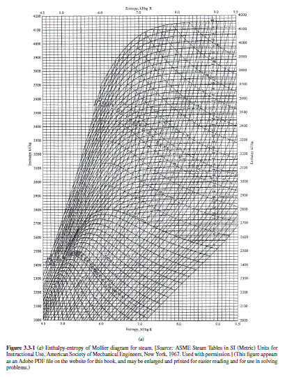
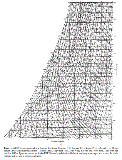
From the steam tables or, less accurately from Fig. 3.3-1, we have
\hat{H}_{1}=3697.9 kJ/kg \quad \hat{H}_{2}= 3278.2 kJ/kg
\hat{V}_{1}=0.4011 \mathrm{~m}^{3} / \mathrm{kg} \quad \hat{V}_{2}=3.103 \mathrm{~m}^{3} / \mathrm{kg}
The velocities at the inlet and outlet to the turbine are calculated from
\text { Volumetric flow rate }=\dot{M} \hat{V}=\frac{\pi d^{2}}{4} v
where d is the pipe diameter. Therefore,
\begin{aligned}v_{1}=\frac{4 \dot{M}_{1} \hat{V}_{1}}{\pi d_{ in }^{2}} &=\frac{4 \cdot 2.5 \frac{ kg }{ s } \cdot 0.4011 \frac{ m ^{3}}{ kg }}{3.14159 \cdot(0.1 m )^{2}}=127.7 \frac{ m }{ s } \\v_{2} &=\frac{4 \dot{M}_{2} \hat{V}_{2}}{\pi d_{ out }^{2}}=158.0 \frac{ m }{ s }\end{aligned}
Therefore, the energy balance yields
\begin{aligned}\dot{W}_{s} &=-\dot{M}_{2}\left(\hat{H}_{2}+\frac{v_{2}^{2}}{2}\right)-\dot{M}_{1}\left(\hat{H}_{1}+\frac{v_{1}^{2}}{2}\right) \\&=-2.5 \frac{ kg }{ s }\left\{\left(\hat{H}_{1}-\hat{H}_{2}\right)+\frac{1}{2}\left(v_{1}^{2}-v_{2}^{2}\right)\right\} \frac{ kJ }{ kg } \\&=-2.5 \frac{ kg }{ s }\left\{419.7 \frac{ kJ }{ kg }+\frac{1}{2}\left(127.7^{2}-158.0^{2}\right) \frac{ m ^{2}}{ s ^{2}} \cdot \frac{1 \frac{ J }{ kg }}{\frac{ m ^{2}}{ s ^{2}}} \cdot \frac{1 kJ }{1000 J }\right\} \\&=-2.5 \frac{ kg }{ s }\{419.7-4.3\} \frac{ kJ }{ kg }=-1038.5 \frac{ kJ }{ s } \quad(=-1329 hp )\end{aligned}
[ The Aspen Plus ^R simulation for this illustration available on the Wiley website for this book in the folder Aspen Illustrations>Chapter 3>3.4-2. The items to notice in that solution are:
1. The isentropic efficiency of the turbine had to be adjusted by trial-and-error to 57.85% to achieve the exit conditions of 400ºC and 1 bar
2. Kinetic and potential energy changes are not easily taken into account using Aspen Plus ^R .
However, they are small for this case, as already shown and can be neglected
3. The Aspen Plus ^R result of 1049.85 kJ/s is in quite good agreement with the result of 1038.5 kJ/s this illustration. The difference of 1% is a result of the differences in the values of the thermodynamic properties in the steam tables and the properties equations used in Aspen Plus ^R .
Comment
If we had completely neglected the kinetic energy terms in this calculation, the error in the work term would be 4.3 kJ/kg, or about 1%. Generally, the contribution of kinetic and potential energy terms can be neglected when there is a significant change in the fluid temperature, as was suggested in Sec. 3.2.


