What does the circuit of Fig. 32-28a do if a coil current of 30 mA or more closes the relay contacts?
Share
Share
Question 32.6: What does the circuit of Fig. 32-28a do if a coil current of...
The Blue Check Mark means that this solution has been answered and checked by an expert. This guarantees that the final answer is accurate.
Learn more on how we answer questions.
Learn more on how we answer questions.
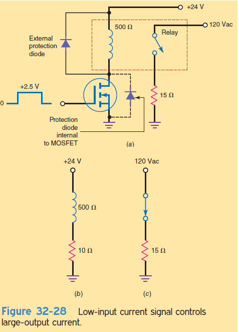
The E-MOSFET is being used to turn a relay on and off. Since the relay coil has a resistance of 500 \Omega , the saturation current is
I_{D(sat)}=\frac{24 V}{500\Omega }=48 mA
Assume this is less than the I_{D(on)} of the MOSFET that has an ON resistance of only 10 \Omega .
Figure 32-28b shows the equivalent circuit for high V_{GS}. The current through the relay coil is approximately 48 mA, more than enough to close the relay. When the relay is closed, the contact circuit looks like Fig. 32-28c. Therefore, the final load current is 8 A (120 V divided by 15 \Omega ).
In Figure 32-28a, an input voltage of only +2.5 V and almost zero input current control a load voltage of 120 Vac and a load current of 8 A. A circuit like this is useful with remote control. The input voltage could be a signal that has been transmitted a long distance through copper wire, fiber-optic cable, or outer space.
Note: The diode across the relay coil is used to protect the transistor from the large voltage spike generated by the coil when the drain current cuts off. The rapidly dropping current creates a huge voltage spike that can damage the transistor. The polarity of this induced voltage is such that it causes the diode to conduct, momentarily clamping the coil voltage to 0.7 V. Some E-MOSFETs have an internal protection diode from source to drain.
Related Answered Questions
With the source grounded, V_{GS} = 0 V and ...
When V_{GS} is low, the LED is off....
For the 2N7000, the most important values are
[lat...
With Formula (32-10),V_{GS(off)}=\frac{-2I_...
The ac drain resistance is
r_d = 3.6 K \Ome...