Question 4.AE.2: A p=2 pole, f=60 Hz synchronous machine (generator, alternat......
A p=2 pole, f=60 Hz synchronous machine (generator, alternator, motor) is rated S_{rat}=16 MVA at a lagging (generating reference system) displacement power factor cos φ=0.8, a line-to-line terminal voltage of V_{L-L}=13,800 V, and a (one-sided) air-gap length of g=0.0127 m. The stator has 48 slots and has a three-phase double-layer, 60° phase-belt winding with 48 armature coils having a short pitch of 2/3. Each coil consists of one turn N_{coil}=1. Sixteen stator coils are connected in series, that is, the number of series turns per phase of the stator (st) are N_{\text{st phase}}=16 (see Fig. E4.2.1). The maximum air-gap flux density at no load (stator current I_{st} phase=0) is B_{\text{st max}}=1 T
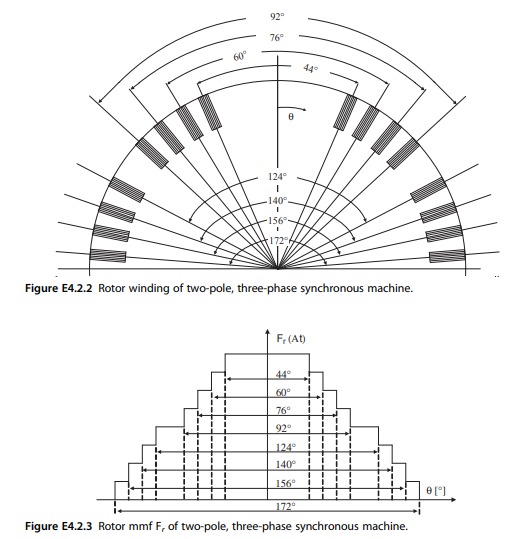
.There are eight field coils per pole (see Fig. E4.2.2) and they are pitched 44-60-76- 92-124-140-156-172 degrees, respectively, as indicated in Fig. E4.2.2. Each field coil has 18 turns. The developed rotor (field) magnetomotive force (mmf) F_r is depicted in Fig. E4.2.3. Note that the field mmf is approximately sinusoidal.
a) Calculate the distribution (breadth) factor of the stator winding k_{s t b}\left(=k_{s t d}\right)
b) Calculate the fundamental pitch factor of the stator winding k_{\text{stp 1}}.
c) Calculate the pitch factor of the rotor (r) winding k_{rp}.
d) Determine the stator flux Φ_{stmax}.
e) Compute the area (area_p) of one pole
f) Compute the field (f) current I_{fo} required at no load.
g) Determine the synchronous (s) reactance (per phase value) X_S of this synchronous machine in ohms.
h) Find the base impedance Z_{base} expressed in ohms.
i) Express the synchronous reactance X_S in per unit (pu).

Learn more on how do we answer questions.
a) Calculation of the distribution (breadth) factor of the stator winding k_{stb}=k_{std} is as follows. The breadth factor is defined for one phase belt as
k_{s t b}=\frac{\text { geometric sum } \sum_{i=1}^8 F_i}{\text { algebraic sum } \sum_{i=1}^8 F_i} (E4.2-1)
It is convenient to evaluate Eq. E4.2-1 graphically, as shown in Fig. E4.2.4. Note that one slot pitch corresponds to 360°/48=7.5°. Thus, one gets from Fig. E4.2.4 the distribution or breadth factor
k_{s t b}=0.96 \text {. } (E4.2-2)
b) Calculation of the pitch factor of the stator winding k_{stp 1} is as follows. One stator turn spans 16 slots out of 24 slots, that is, it has a pitch of (2/3); therefore, one obtains for the fundamental n=1
k_{\text {stp } 1}=\left|\sin \left(\frac{n \beta}{2}\right)\right|=\left|\sin \left(\frac{(1)(120)}{2}\right)\right|=0.866 (E4.2-3)
or for the 5th harmonic n=5
k_{s t p 5}=\left|\sin \left(\frac{(5)(120)}{2}\right)\right|=0.866 .The 5th harmonic is not attenuated; therefore, the choice of a 2/3 winding pitch is not recommended.
The total fundamental winding factor of the stator winding is now
c) Calculate the pitch factor of the rotor (r) winding k_{rp} as follows. The fundamental (n=1) pitch-factor of the rotor winding is correspondingly
\begin{aligned} & k_r=\left\{\left|\sum_{i=1}^8 \sin \left(\frac{n \beta_i}{2}\right)\right|\right\} / 8,\quad (E4.2-4) \\ & k_{r p}=\left\{\left|\sin \left(\frac{44^{\circ}}{2}\right)\right|+\left|\sin \left(\frac{60^{\circ}}{2}\right)\right|+\left|\sin \left(\frac{76^{\circ}}{2}\right)\right|+\left|\sin \left(\frac{92^{\circ}}{2}\right)\right|+\left|\sin \left(\frac{124^{\circ}}{2}\right)\right|\right. \\ &\left.+\left|\sin \left(\frac{140^{\circ}}{2}\right)\right|+\left|\sin \left(\frac{156^{\circ}}{2}\right)\right|+\left|\sin \left(\frac{172^{\circ}}{2}\right)\right|\right\} / 8 \Rightarrow k_m=0.751 . \end{aligned}d) Determination of the stator flux Φ_{stmax} is as follows. The induced voltage in the stator winding per phase is
E_{p h t}=4.44 \cdot f \cdot N_{s t p h t} \cdot k_{s t b} \cdot k_{s t p 1} \cdot \Phi_{s t \operatorname{tax}} (E4.2-5)
or one obtains for the stator flux
\Phi_{s t \max }=\frac{E_{L-L}}{\sqrt{3} \cdot 4.44 \cdot f \cdot N_{s t p h l} \cdot k_{s t b} \cdot k_{s t p 1}} (E4.2-6)
with E_{L-L}=V_{L-L}=13,800 V at no load, one gets the flux for no-load condition:
\Phi_{s t \text { max }}^{\text {no-load }}=\frac{13800}{\sqrt{3}(4.44)(60)(16)(0.96)(0.866)}=2.25 \frac{\mathrm{Wb}}{\text { pole }} . (E4.2-7)
e) Compute the area (area_p) of one pole:
\operatorname{area}_p=\frac{\Phi_{\text {stmax }}^{\mathrm{no}-\mathrm{load}}}{B_{\max }}=2.25 \mathrm{~m}^2 \text {. } (E4.2-8)
f) Compute the field (f ) current I_{fo} required at no load:
I_{f o}=\frac{B_{s t \text { max }} \cdot p \cdot g \cdot \pi}{4 \cdot \mu_0 \cdot k_{r p} \cdot N_{\text {rot }}}=\frac{1(2)(0.0127)(\pi)}{4\left(4 \pi \times 10^{-7}\right)(0.751)(288)}=73.4 A \text {. } (E4.2-9)
g) Determine the synchronous (s) reactance (per phase value) XS in ohms. The selfinductance of phase a is
\begin{gathered} L_{a a}=\frac{\lambda_{a a}}{i_a}=\frac{N_{s t} \cdot \varphi_{s t \max }}{i_a}=\frac{N_{s t} \cdot B_{s t \max } \cdot \text { area }_p}{i_a} \\ =\frac{\mu_0 \cdot 4 \cdot k_{s t b} \cdot k_{s t p} \cdot\left(\mathrm{N}_{\mathrm{stph}}\right)^2 \cdot \text { area }_p}{p \cdot g \cdot \pi} \\ L_{a a}=\frac{4 \pi \times 10^{-7}(4)(0.96)(0.866)(16)^2(2.25)}{2(0.0127)(\pi)}=30.16 \mathrm{mH} . \end{gathered} (E4.2-10)
According to Concordia [7]
L_d=L_{a a}+L_{a b}+1.5 L_{a a 2} (E4.2-11)
Neglecting L_{a a 2} \text { and } L_{a a} \approx L_{a b} \text { one gets for the synchronous inductance } L_d.
L_d \approx 2 \cdot L_{a a}=60.33 \mathrm{mH} .The synchronous reactance of the round-rotor machine is
X_S=\omega L_d=\omega L_S=22.74 \Omega (E4.2-12)
The base voltage is
V_{\text {base }}=\frac{V_{L-L}}{\sqrt{3}}=V_{\text {phase }}=7,967 \mathrm{~V} \text {. } (E4.2-13)
The base apparent power is per phase
S_{\text {base }}=S_{\text {phase }}=\frac{S_{\text {rat }}}{3}=5.33 \mathrm{MVA} (E4.2-14)
and the base current is
I_{\text {base }}=I_{\text {phase }}=\frac{S_{\text {base }}}{V_{\text {base }}}=669 \mathrm{~A} . (E4.2-15)
h) Find the base impedance Z_{base} expressed in ohms. The base impedance becomes
Z_{\text {base }}=\frac{V_{\text {base }}}{I_{\text {base }}}=11.9 \Omega . (E4.2-16)
i) Express the synchronous reactance X_S in per unit (pu). The per-unit synchronous reactance is now
X_S^{p u}=\frac{X_S}{Z_{\text {base }}}=\frac{22.74}{11.9}=1.91 \mathrm{pu} . (E4.2-17)
