Question 12.5: Design Analysis of a Worm Gear Speed Reducer A worm gearset ......
Design Analysis of a Worm Gear Speed Reducer
A worm gearset and its associated geometric quantities are schematically shown in Figure 12.19. Estimate:
a. The heat-dissipation capacity.
b. The efficiency.
c. The input and output horsepower.
Assumptions: The gearset is designed for continuous operation based on a limiting 100°F temperature rise of the housing without fan.

Learn more on how do we answer questions.
The speed ratio of the worm gearset is
r_s=\frac{N_w}{N_g}=\frac{4}{60}=\frac{1}{15}
a. Through the use of Equation (12.24),
A=0.3 c^{1.7} (12.24)
A=0.3 c^{1.7}=0.3(8)^{1.7}=10.29 ft ^2
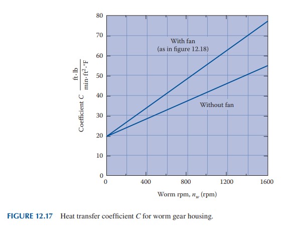
From Figure 12.17, we have
C=42 lb \cdot ft /\left(\min \cdot ft ^2 \cdot{ }^{\circ} F \right)
Carrying the data into Equation (12.25),
hp _d=\frac{C A \Delta t}{33,000} (12.25)
hp _d=\frac{C A \Delta t}{33,000}=\frac{42(10.29)(100)}{33,000}=1.31
b. The pitch-line velocity of the worm is
V_w=\frac{\pi d_w n_w}{12}=\frac{\pi(3)(1000)}{12}=785.4 fpm
Applying Equation (12.28),
V_s=\frac{V_w}{\cos \lambda} (12.28)
V_s=\frac{V_w}{\cos \lambda}=\frac{785.4}{\cos 15^{\circ}}=812 fpm
By Table 12.3, f =0.0238. Introducing the numerical values into Equation (12.27),
e=\frac{\cos \phi_n-f \tan \lambda}{\cos \phi_n-f \cot \lambda} (12.27)
e=\frac{\cos 25^{\circ}-0.0238\left(\tan 15^{\circ}\right)}{\cos 25^{\circ}+0.0238\left(\cot 15^{\circ}\right)}=0.904 \quad \text { or } \quad 90.4 \%
c. Using Equation (12.26), the input horsepower is equal to
hp _i=\frac{ hp _d}{1-e} (12.26)
hp _i=\frac{ hp _d}{1-e}=\frac{1.31}{1-0.0904}=13.65
The output horsepower is then
hp _o=13.65-1.31=12.3
Comments: Because of the sliding friction inherent in the tooth action, usually worm gearsets have significantly lower efficiencies than those of spur gear drives. The latter can have efficiencies as high as 98% (Section 11.1).
| TABLE 12.3 Worm Gear Coefficient of Friction f for Various Sliding Velocities V_s |
|||||
| V_s( fpm ) | f | V_s( fpm ) | f | V_s( fpm ) | f |
| 0 | 0.150 | 120 | 0.0519 | 1200 | 0.0200 |
| 1 | 0.115 | 140 | 0.0498 | 1400 | 0.0186 |
| 2 | 0.110 | 160 | 0.0477 | 1600 | 0.0175 |
| 5 | 0.099 | 180 | 0.0456 | 1800 | 0.0167 |
| 10 | 0.090 | 200 | 0.0435 | 2000 | 0.0160 |
| 20 | 0.080 | 250 | 0.0400 | 2200 | 0.0154 |
| 30 | 0.073 | 300 | 0.0365 | 2400 | 0.0149 |
| 40 | 0.0691 | 400 | 0.0327 | 2600 | 0.0146 |
| 50 | 0.0654 | 500 | 0.0295 | 2800 | 0.0143 |
| 60 | 0.0620 | 600 | 0.0274 | 3000 | 0.0140 |
| 70 | 0.0600 | 700 | 0.0255 | 4000 | 0.0131 |
| 80 | 0.0580 | 800 | 0.0240 | 5000 | 0.0126 |
| 90 | 0.0560 | 900 | 0.0227 | 6000 | 0.0122 |
| 100 | 0.0540 | 1000 | 0.0217 | — | — |
| Source: From ANSI/AGMA Standard 6034-A87. | |||||