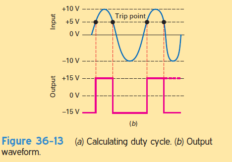
What is the duty cycle of the output waveform in Fig. 36-13b?
Share
Share
Question 36.4: What is the duty cycle of the output waveform in Fig. 36-13b...
The Blue Check Mark means that this solution has been answered and checked by an expert. This guarantees that the final answer is accurate.
Learn more on how we answer questions.
Learn more on how we answer questions.
Recall that the duty cycle is defined as the pulse width divided by the period. Duty cycle equals the conduction angle divided by 360°.
In Fig. 36-13b, the sine wave has a peak value of 10 V. Therefore, the input voltage is given by
v_{in} = 10 \sin \thetaThe rectangular output switches states when the input voltage crosses +5 V. At this point, the foregoing equation becomes
5 = 10 \sin \thetaNow, we can solve for the angle \theta where switching occurs:
\sin \theta = 0.5or
\theta = arcsin 0.5= 30° and 150°
The first solution, \theta = 30°, is where the output switches from low to high. The second solution, \theta = 150°, is where the output switches from high to low. The duty cycle is
D=\frac{conduction angle}{360°}=\frac{150°-30°}{360°}= 0.333The duty cycle in Fig. 36-13b can be expressed as 33.3%.
Related Answered Questions
This is a noninverting first-order low-pass filter...
The feedback fraction is
B=\frac{18k\Omega ...
With Formula (36-4),B=\frac{R_1}{R_1+R_2 }[...
This is one way to create a 60-Hz clock, a square-...
With Formulas (36-32) f_0=\frac{1}{2\pi RC}...
A=\frac{-R_2}{2R_1}=\frac{-36 k\Omega }{2(1...
This is an inverting first-order low-pass filter. ...
With the equations shown in Fig. 36-25, we can ana...