Question 9.9: A simple beam AB of a span length L has an overhang BC of le......
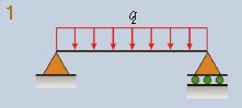
A simple beam AB of a span length L has an overhang BC of length a (Fig. 9-21a).
The beam supports a uniform load of intensity q throughout its length.
Obtain a formula for the deflection δC at the end of the overhang (Fig. 9-21c).
Note: The beam has constant flexural rigidity EI.


Learn more on how do we answer questions.
Use a four-step problem-solving approach.
1. Conceptualize: Find the deflection of point C by imagining the overhang BC (Fig. 9-21a) to be a cantilever beam subjected to two actions. The first action is the rotation of the support of the cantilever through an angle θB, which is the angle of rotation of beam ABC at support B (Fig. 9-21c). (Assume that a clockwise angle θB is positive.) This angle of rotation causes a rigid-body rotation of the overhang BC, resulting in a downward displacement δ1 of point C.
The second action is the bending of BC as a cantilever beam supporting a uniform load. This bending produces an additional downward displacement δ2 (Fig. 9-21c). The superposition of these two displacements gives the total displacement δC at point C.
2. Categorize:
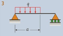
Deflection δ1: Begin by finding the deflection δ1 caused by the angle of rotation θB at point B. To find this angle, observe that part AB of the beam is in the same condition as a simple beam (Fig. 9-21b) subjected to the following loads: a uniform load of intensity q, a couple MB (equal to qa2/2), and a vertical load P (equal to qa). Only the loads q and MB produce angles of rotation at end B of this simple beam. These angles are found from Cases 1 and 7 of Table H-2, Appendix H. Thus, the angle θB is
θB=−24EIqL3+3EIMBL=−24EIqL3+6EIqa2L=24EIqL(4a2−L2)(9-67)
in which a clockwise angle is positive, as shown in Fig. 9-21c.
The downward deflection δ1 of point C, due solely to the angle of rotation θB, is equal to the length of the overhang times the angle (Fig. 9-21c):
δ1=aθB=24ELqaL(4a2−L2)(a)
Deflection δ2: Bending of the overhang BC produces an additional downward deflection δ2 at point C. This deflection is equal to the deflection of a cantilever beam of length a subjected to a uniform load of intensity q (see Case 1 of Table H-1):
δ2=8EIqa4(b)
3. Analyze:
Deflection δC: The total downward deflection of point C is the algebraic sum of δ1 and δ2:
δC=δ1+δ2=24EIqaL(4a2−L2)+8EIqa4=24EIqa[L(4a2–L2)+3a3]
or
δC=24EIqa(a+L)(3a2+aL−L2)(9-68)
4. Finalize: In the preceding equation, the deflection δC may be upward or downward, depending upon the relative magnitudes of the lengths L and a. If a is relatively large, the last term in the equation (the three-term expression in parentheses) is positive, and the deflection δC is downward. If a is relatively small, the last term is negative, and the deflection is upward. The deflection is zero when the last term is equal to zero:
3a2+aL–L2=0
or
a=6L(13−1)=0.4343L(c)
From this result, note that if a is greater than 0.4343L, the deflection of point C is downward; if a is less than 0.4343L, the deflection is upward.
Deflection curve: The shape of the deflection curve for the beam in this example is shown in Fig. 9-21c for the case where a is large enough (a > 0.4343L) to produce a downward deflection at C and small enough (a < L) to ensure that the reaction at A is upward. Under these conditions, the beam has a positive bending moment between support A and a point such as D. The deflection curve in region AD is concave upward (positive curvature). From D to C, the bending moment is negative; therefore, the deflection curve is concave downward (negative curvature).
Point of inflection: At point D, the curvature of the deflection curve is zero because the bending moment is zero. A point such as D, where the curvature and bending moment change signs, is called a point of inflection (or point of contraflexure). The bending moment M and the second derivative d2v/dx2 always vanish at an inflection point.
However, a point where M and d2v/dx2 equal zero is not necessarily an inflection point because it is possible for those quantities to be zero without changing signs at that point; for example, they could have maximum or minimum values.
| Table H-2 | |
| Deflections and Slopes of Simple Beams | |
 |
Notation: v = deflection in the y direction (positive upward) v’ = dv/dx = slope of the deflection curve δC=−v(L/2) = deflection at end B of the beam (positive downward) x1 = distance from support A to point of maximum deflection δmax=−vmax = maximum deflection (positive downward) θA=−v′(0) = angle of rotation at left-hand end of the beam (positive clockwise) θB=v′(L) = angle of rotation at right-hand end of the beam (positive counterclockwise) EI = constant |
 |
ν=−24EIqx(L3−2Lx2+x3)ν′=−24EIq(L3−6Lx2+4x3) δC=δmax=−384EI5qL4θA=θB=24EIqL3 |
 |
ν=−384EIqx(9L3–24Lx2+16x3)(0≤x≤2L)ν′=−384EIq(9L3–72Lx2+64x3)(0≤x≤2L)ν=−384EIqL(8x3–24Lx2+17L2x–L3)(2L≤x≤L)ν′=−384EIqL(24x2–48Lx+17L2) (2L≤x≤L) δC=−768EI5qL4θA=128EI3qL3θB=384EI7qL3 |
 |
ν=−24LEIqx(a4–4a3L+4a2L2+2a2x2–4aLx2+Lx3)(0≤x≤a)ν′=−24LEIq(a4–4a3L+6a2L2+6a2x2–12aLx2– 4Lx3)(0≤x≤a)ν=−24LEIqa2(−a2L+4L2x+a2x−6Lx2+2x3)(a≤x≤L)ν′=−24LEIqA2(4L2+a2–12Lx+6x2)(a≤x≤L) θA=24LEIqa2(2L–a)2θB=24LEIqa2(2L2–a2) |
 |
v=−48EIPx(3L2−4x2)v′=−16EIP(L2−4x2)(0≤x≤2L)δC=δmax=48EIPL3θA=θB=16EIPL2 |
 |
ν=−6LEIPbx(L2−b2−x2)ν′=−6LEIPb(L2−b2−3x2)(0≤x≤a)θA=6LEIPab(L+a)θB=6LEIPab(L+a)Ifa≥b,δC=48EIPb(3L2–4b2)Ifa≤b,δC=48EIPa(3L2–4a2)Ifa≥b,x1=3L2–b2andδmax=93LEIPb(L2–b2)3/2 |
 |
v=−6EIPx(3aL–3a2–x2)v′=−2EIP(aL–a2–x2)(0≤x≤a)v=−6EIPa(3Lx–3x2–a2)v′=−2EIPa(L–2x)(a≤x≤L–a)δC=δmax=24EIPa(3L2–4a2)θA=θB=2EIPa(L−a) |
 |
ν=−6LEIM0x(2L2–3Lx+x2) ν′=−6LEIM0(2L2−6Lx+3x2)δC=16EIM0L2θA=3EIM0L θB=6EIM0Lx1=L⎩⎪⎪⎪⎪⎪⎧1–33⎭⎪⎪⎪⎪⎪⎫andδmax=93EIM0L2 |
 |
ν=−24LEIM0x(L2– 4x2) ν′=−24LEIM0(L2−12x2)(0≤x≤2L)δC=0 θA=24EIMoL θB=24EIM0L |
 |
v=−6LEIM0x(6aL–3a2–2L2–x2)(0≤x≤a) v′=−6LEIM0(6aL–3a2–2L2–3x2)(0≤x≤a) Atx=a:v=−3LEIM0ab(2a–L)v′=−3LEIM0(3aL–3a2–L2)θA=6LEIM0(6aL–3a2–2L2)θB=6LEIM0(3a2–L2) |
 |
ν=−2EIM0x(L– x) ν′=−2EIM0(L–2x)δC=δmax=8EIM0L2θA=θB=2EIMoL |
 |
v=−360LEIq0x(7L4–10L2x2+3Lx4)v′=−360LEIq0(7L4–30L2x2+15x4) δC=768EI5q0L4θA=360EI7q0L3θB=45EIq0L3x1=0.5193Lδmax=0.00652EIq0L4 |
 |
v=−960LEIq0x(5L2–4x2)2( 0≤x≤2L) v′=−192LEIq0(5L2–4x2)(L2–4x2)( 0≤x≤2L) δC=δmax=120EIq0L4θA=θB=192EI5q0L3 |
 |
v=−π4EIq0L4sinLπx v′=−π3EIq0L3cosLπx δC=δmax=π4EIq0L4θA=θB=π3EIq0L3 |
| Table H-1 | |
| Deflections and Slopes of Cantilever Beams | |
 |
Notation: v = deflection in the y direction (positive upward) v’ = dv/dx = slope of the deflection curve δB=−v(L) = deflection at end B of the beam (positive downward) θB=−v′(L) = angle of rotation at end B of the beam (positive clockwise) EI = constant |
 |
ν=−24EIqx2(6L2−4Lx+x2)v′=6EIqx(3L2–3Lx+x2)δB=8EIqL4θB=6EIqL3 |
 |
v=−24EIqx2(6a2−4ax+x2)(0≤x≤a)v′=−6EIqx(3a2−3ax+x2)(0≤x≤a) v=−24EIqa3(4x–a) v′=−6EIqa3(a≤x≤L)Atx=a:v=−8EIqa4v′=−6EIqa3δB=24EIqa3(4L–a)θB=6EIqa3 |
 |
v=−12EIqbx2(6L+3a–2x)(0≤x≤a)v′=−2EIqbx(L+a–x)(0≤x≤a) v=−24EIq(x4−4Lx3+6L2x2–4a3x+a4)(a≤x≤L)v′=−6EIq(x3−3Lx2+3L2x–a3)(a≤x≤L)ATx=a:v=−12EIqa2b(3L+a)v′=−2EIqabLδB=24EIq(3L4−4a3L+a4)θB=6EIq(L3–a3) |
 |
v=−6EIPx2(3L–x)v′=−2EIPx(2L–x)δB=3EIPL3θB=2EIPL2 |
 |
v=−6EIPx2(3a–x)v′=−2EIPx(2a−x)(0≤x≤a) v=−6EIPa2(3x–a) v′=−2EIPa2(a≤x≤L)Atx=a:v=−3EIPa3v′=−2EIPa2δB=6EIPa2(3L–a)θB=2EIPa2 |
 |
ν=−2EIM0x2ν′=−EIM0xδB=−2EIM0L2θB=−EIM0L |
 |
v=−2EIM0x2v′=−EIM0x(0≤x≤a)v=−2EIM0a(2x–a)v′=−EIM0a(0≤x≤a) Atx=a:v=−2EIM0a2v′=−EIM0aδB=2EIM0a(2L–a)θB=EIM0a |
 |
v=−120LEIq0x2(10L3–10L2x+5Lx2–x3)v′=−24LEIq0x(4L3−6L2x+4Lx2–x3) δB=30EIq0L4θB=24EIq0L3 |
 |
v=−120LEIq0x2(20L3–10L2x+ x3)v′=−24LEIq0x(8L3−6L2x+x3) δB=120EI11q0L4θB=8EIq0L3 |
 |
v=−3π4EIq0L(48L3cos2Lπx–48L3+3π3Lx2–π3x3)v′=−π3EIq0L(2π2Lx–π2x2–8L2sin2Lπx) δB=3π4EI2q0L4(π3–24)θB=π3EIq0L3(π2–8) |