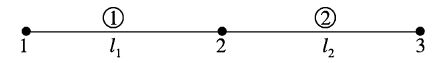
Two-element FE model is shown below.
The connectivity table is given by
Element 1 Stiffness matrix is
k_e^{(1)}=\frac{2 E I}{(100)^3}\left[\begin{array}{cccc}12 & 600 & -12 & 600 \\600 & 40000 & -600 & 20000 \\-12 & -600 & 12 & -600 \\600 & 20000 & -600 & 40000\end{array}\right]
k_e^{(1)}=\frac{E I}{(100)^3}\left[\begin{array}{cccc}1 & 2 & 3 & 4 \\-\frac{2}{24} & 1200 & -24 & 1200 \\1200 & 80,000 & -1200 & 40,000 \\-24 & -1200 & 24 & -1200 \\1200 & 40,000 & -1200 & 80,000\end{array}\right] ^{\leftarrow \text { dof }}

The assembled stiffness matrix is

K=\frac{200 \times 10^3 \times 2 \times 10^5}{10^6}\left[\begin{array}{cccccc}1 & 2 & 3 & 4 & 5 & 6 \\24 & 1200 & -24 & 1200 & 0 & 0 \\1200 & 80,000 & -1200 & 40,000 & 0 & 0 \\& & 36 & -600 & -12 & 600 \\& & & 120,000 & -600 & 2000 \\& \text { symmetric } & & & 12 & -600 \\& & & & & 40,000\end{array}\right]^{ → \text{ Global dof}}
For element 1: Q_1 Q_2 Q_3 Q_4
for element 2: Q_3 Q_4 Q_5 Q_6
Hence Q_1=Q_2=0
The force vector is
F=\left[0,10 \times 10^4, 0,5 \times 10^4,-500,0\right]^T
Q=\left[0,0, Q_3, Q_4, Q_5, Q_6\right]^T
How using the elimination approach, the finite elements equations are
\frac{E I}{(100)^3}\left[\begin{array}{cccc}36 & -600 & -12 & 600 \\-600 & 120,000 & -600 & 20,000 \\-12 & -600 & 12 & -600 \\600 & 20,000 & -600 & 40,000\end{array}\right]\left\{\begin{array}{l}Q_3 \\Q_4 \\Q_5 \\Q_6\end{array}\right\}=\left\{\begin{array}{c}0 \\-50,000 \\-500 \\0\end{array}\right\}
\left\{\begin{array}{l}Q_3 \\Q_4 \\Q_5 \\Q_6\end{array}\right\}=10^6 \times\left[\begin{array}{cccc}4.167 & 0.063 & 10.417 & 0.063 \\0.063 & 0.0013 & 0.188 & 0.0013 \\10.417 & 0.188 & 37.5 & 0.313 \\0.063 & 0.0013 & 0.313 & 0.00375\end{array}\right]\left\{\begin{array}{c}0 \\-50,000 \\-500 \\0\end{array}\right\}
Solving, we get
Q_3=-0.00833, Q_4=-0.000156
Q_5=-0.028125, Q_6=-0.000218
The nodal displacement for elements 1 and 2 are:
q^{(1)}=[0,0,-0.00833,-0.000156]^T
q^{(2)}=[-0.00833,-0.000156,-0.028125,-0.000218]^T
The vertical deflection at free end is obtained from the relation (taking element 2)
V=H q
V=H_1 q_3+\frac{l_e}{2} H_2 q_4+H_3 q_5+\frac{l_e}{2} H_4 q_6
Here H = shape function
H_1=\frac{1}{4}(1-\xi)^2(2+\xi)=\frac{1}{2} \text { for } \xi=+1
For an element. \xi varies from -1 to + 1 as shown in the figure below .
Hence, H_1=H_2=H_4=0 \text { and } H_3=1
\therefore \quad V=H_3 q_5
=-1 \times 0.020125=-0.028125 \mathrm{~mm}