Question 10.1: A propped cantilever beam AB of a length L supports a unifor......
A propped cantilever beam AB of a length L supports a uniform load of intensity q (Fig. 10-6). Analyze this beam by solving the second-order differential equation of the deflection curve (the bending-moment equation). Determine the reactions, shear forces, bending moments, slopes, and deflections of the beam.

Learn more on how do we answer questions.
Use a four-step problem-solving approach.
1. Conceptualize [hypothesize, sketch]: Because the load on this beam acts in the vertical direction (Fig. 10-6), there is no horizontal reaction at the fixed support. Therefore, the beam has three unknown reactions (M_A, R_A, ~ and ~ R_B). Only two equations of equilibrium are available for determining these reactions; therefore, the beam is statically indeterminate to the first degree.
2. Categorize [simplify, classify]: To analyze this beam by solving the bending-moment equation, begin with a general expression for the moment. This expression is in terms of both the load and the selected redundant.
Redundant reaction: Choose the reaction R_B at the simple support as the redundant.
Then, by considering the equilibrium of the entire beam, express the other two reactions in terms of R_B:
\quad\quad R_{A}=q L-R_{B}\qquad M_{A}=\frac{q L^{2}}{2}-R_{B}L\quad\quad(a,b)
Bending moment: The bending moment M at distance x from the fixed support is expressed in terms of the reactions as
\quad\quad M=R_{A}x-M_{A}-{\frac{q x^{2}}{2}}\quad\quad(c)
This equation is obtained by constructing a free-body diagram of part of the beam and solving an equation of equilibrium.
Substitute into Eq. (c) from Eqs. (a) and (b) to obtain the bending moment in terms of the load and the redundant reaction:
\quad\quad {M}={q}L x-R_{B}x-{\frac{q L^{2}}{2}}+R_{B}L-{\frac{q x^{2}}{2}}\quad\quad(d)
3. Analyze [evaluate; select relevant equations; carry out mathematical solution]:
Differential equation: The second-order differential equation of the deflection curve [Eq. (9-16a)] now becomes
\quad\quad El\nu^{\prime\prime}=M=q L x-R_{B}x-{\frac{q L^{2}}{2}}+R_{B}L-{\frac{q x^{2}}{2}}\quad\quad(e)
After two successive integrations, the following equations are obtained for the slopes and deflections of the beam:
\quad\quad Elv^{\prime}=\frac{q L x^{2}}{2}-\frac{R_{B}x^{2}}{2}-\frac{q L^{2}x}{2}+R_{B}L_x – \frac{q x^{3}}{6}+C_{1} \quad\quad (f) \\ El\nu={\frac{q L x^{3}}{6}}-{\frac{{R_{B}}x^{3}}{6}}-{\frac{q L^{2}x^{2}}{4}}+{\frac{{R_{B}}L x^{2}}{2}}-{\frac{q x^{4}}{24}}+C_{1}x+C_{2}\quad\quad(g)
These equations contain three unknown quantities (C_1, C_2, ~ and ~ R_B).
Boundary conditions: Three boundary conditions pertaining to the deflections and slopes of the beam are apparent from an inspection of Fig. 10-6. These conditions are (1) the deflection at the fixed support is zero, (2) the slope at the fixed support is zero, and (3) the deflection at the simple support is zero.
Thus,
\quad\quad\nu(0)=0\qquad v^{\prime}(0)=0\qquad v(L)=0
Apply these conditions to the equations for slopes and deflections given in Eqs. (f) and (g) to find that C_1 = 0, C_2 = 0, and
\quad\quad R_{B}={\frac{3q L}{8}}\quad\quad(10-1)
Thus, the redundant reaction R_B is now known.
Reactions: With the value of the redundant established, the remaining reactions from Eqs. (a) and (b) are
\quad\quad R_{A}=\frac{5q L}{8}\qquad M_{A}=\frac{q L^{2}}{8}\quad\quad(10-2a,b)
Knowing these reactions, the shear forces and bending moments in the beam can now be found.
Shear forces and bending moments: These quantities are obtained by the usual techniques involving free-body diagrams and equations of equilibrium. The results are
\quad\quad V=R_{{A}} – q x = \frac{5{{q}}L}{8} – {q}{x}\quad\quad (10-3) \\ M=R_{A}x-M_{A}-{\frac{q x^{2}}{2}}={\frac{5q L x}{8}}-{\frac{q L^{2}}{8}}-{\frac{q x^{2}}{2}} \quad\quad (10-4)
Shear-force and bending-moment diagrams for the beam are drawn with the aid of these equations (see Fig. 10-7).
From the diagrams, note that the maximum shear force occurs at the fixed support and is equal to
\quad\quad V_{\mathrm{max}}={\frac{\,5 q L\,}{8}}\quad\quad(10-5)
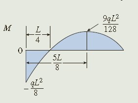
Also, the maximum positive and negative bending moments are
\quad\quad M_{\mathrm{pos}}={\frac{9q L^{2}}{128}}\qquad M_{\mathrm{neg}}=-{\frac{q L^{2}}{8}}\quad\quad(10-6a,b)
Finally, note that the bending moment is equal to zero at distance x = L/4 from the fixed support.
Slopes and deflections of the beam: Return to Eqs. (f) and (g) for the slopes and deflections; now substitute the values of the constants of integration (C_1 = 0 ~ and ~ C_2 = 0) as well as the expression for the redundant R_B [Eq. (10-1)] and obtain
v^{'}={\frac{q x}{48E I}}(-6L^{2}+15L x-8x^{2})\quad\quad(10-7) \\ \nu=-\frac{q x^{2}}{48E I}(3L^{2}-5L x+2x^{2})\quad\quad(10-8)
The deflected shape of the beam as obtained from Eq. (10-8) is shown in Fig. 10-8.
To determine the maximum deflection of the beam, set the slope [Eq. (10-7)] equal to zero and solve for the distance x_1 to the point where this deflection occurs:
\quad\quad v^{\prime}=0\ \ \mathrm{or}-6L^{2}+15 L x-8x^{2}=0
from which
x_{1}={\frac{15-{\sqrt{33}}}{16}}L=0.5735L\quad\quad(10-9)
Substitute this value of x into the equation for the deflection [Eq. (10-8)] and also change the sign to get the maximum deflection:
The point of inflection is located where the bending moment is equal to zero, that is, where x = L / 4. The corresponding deflection \delta_0 of the beam [from Eq. (10-8)] is
\delta_{0}=-{\nu(L/4)}=\frac{5q L^{4}}{2048E I}=0.002441{\frac{q L^{4}}{EI}}\quad\quad(10-11)
Note that when x < L/4, both the curvature and the bending moment are negative, and when x > L/4, the curvature and bending moment are positive.
To determine the angle of rotation \theta_B at the simply supported end of the beam, use Eq. (10-7), as
\theta_{B}=v^{\prime}(L)=\frac{q L^{3}}{48E I}\quad\quad(10-12)
Slopes and deflections at other points along the axis of the beam can be
obtained by similar procedures.
4. Finalize [conclude; examine answer—Does it make sense? Are units correct? How does it compare to similar problem solutions?]: This example presents the analysis of the beam by taking the reaction R_B (Fig. 10-6) as the redundant reaction. An alternative approach is to take the reactive moment M_A as the redundant. Then express the bending moment M in terms of M_A, substitute the resulting expression into the second-order differential equation, and solve as before. Still another approach is to begin with the fourth-order differential equation, as illustrated in the next example.