Question 10.2: The fixed-end beam ACB shown in Fig. 10-9 supports a concent......
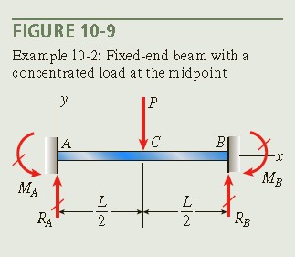
The fixed-end beam ACB shown in Fig. 10-9 supports a concentrated load P at the midpoint. Analyze this beam by solving the fourth-order differential equation of the deflection curve (the load equation). Determine the reactions, shear forces, bending moments, slopes, and deflections of the beam.
Learn more on how do we answer questions.
Use a four-step problem-solving approach.
1. Conceptualize: Because the load on this beam acts only in the vertical direction, there are no horizontal reactions at the supports. Therefore, the beam has four unknown reactions—two at each support. Since only two equations of equilibrium are available, the beam is statically indeterminate to the second degree.
2. Categorize: The analysis can be simplified by observing from the symmetry of the beam and its loading that the forces and moments at supports A and B are equal, that is,
R_{A}=R_{B}\quad{\mathrm{and}}\quad M_{A}=M_{B}
The vertical reactions at the supports are equal, so from equilibrium of forces in the vertical direction, each force is equal to P/2:
R_{A}=R_{B}={\frac{P}{2}}\quad\quad(10-13)
Thus, the only unknown quantities that remain are the moment reactions M_A ~ and ~ M_B. For convenience, select the moment M_A as the redundant quantity.
3. Analyze:
Differential equation: Because there is no load acting on the beam between points A and C, the fourth-order differential equation [Eq. (9-19c)] for the left-hand half of the beam is
EIv^{\prime\prime\prime\prime}\:=\:-q\:=\:0\:\:\:\:\:\:(0\lt \times\lt L/2)\quad\quad(a)
Successive integrations of this equation yield the following equations, which are valid for the left-hand half of the beam:
\begin{array}{c}{{{E}{{I}}{{\nu}}^{\prime\prime\prime} = C_{1}}} \quad\quad (b)\\ {{{E}{{I}}{{\nu}}^{\prime\prime} = C_{1}x+C_{2}}} \quad\quad (c) \\ {{E I\nu^{\prime}={\displaystyle\frac{C_{1}x^{2}}{2}}+C_{2}x+C_{3}}} \quad\quad (d)\\ {{E I\nu={\displaystyle\frac{C_{1}x^{3}}{6}}+{\displaystyle\frac{C_{2}x^{2}}{2}}+C_{3}x+C_{4}}\quad\quad (e)}\end{array}
These equations contain four unknown constants of integration. There are now five unknowns (C_1, C_2, C_3, C_4, ~ and ~ M_A), so five boundary conditions are needed.
Boundary conditions: The boundary conditions applicable to the left-hand half of the beam are
i. The shear force in the left-hand segment of the beam is equal to R_A , or P/2. Therefore, from Eq. (9-16b)
\quad\quad E I\nu^{\prime\prime\prime}=V=\frac{{P}}{2}
Combine this equation with Eq. (b) to obtain C_1 = P/2.
ii. The bending moment at the left-hand support is equal to -M_A. Therefore, from Eq. (9-16a),
EI\nu^{\prime\prime}=M=-M_{A}\quad\mathrm{at}\quad x=0
Combining this equation with Eq. (c) leads to C_2 = -MA.
iii. The slope of the beam at the left-hand support (x = 0) is equal to zero.
Therefore, Eq. (d) yields C_3 = 0.
iv. The slope of the beam at the midpoint (x = L/2) is also equal to zero (from symmetry). Therefore, from Eq. (d),
M_{A}=M_{_{B}}={\frac{P L}{8}}\quad\quad(10-14)
Thus, the reactive moments at the ends of the beam have been determined.
v. The deflection of the beam at the left-hand support (x = 0) is equal to zero. Therefore, from Eq. (e), C_4 = 0.
In summary, the four constants of integration are
C_{1}={\frac{P}{2}}\ \ C_{2}=-M_{A}=-{\frac{P L}{8}}\ \ \ C_{3}=0\ \ \ C_{4}=0\quad\quad(f,g,h,i)
Shear forces and bending moments: The shear forces and bending moments are found by substituting the appropriate constants of integration into Eqs. (b) and (c). The results are
Since the reactions of the beam are known, these expressions also can be obtained directly from free-body diagrams and equations of equilibrium.
The shear-force and bending moment diagrams are shown in Fig. 10-10.
Slopes and deflections: The slopes and deflections in the lefthand half of the beam can be found from Eqs. (d) and (e) by substituting the expressions for the constants of integration.
The resulting expressions are
v^\prime=-\frac{P x}{8E I}(L-2x)\qquad(0\leq x\leq L/2)\quad\quad (10-17) \\ v =-\frac{P x^2}{48E I}(3L-4x)\qquad(0\leq x\leq L/2)\quad\quad (10-18)
The deflection curve of the beam is shown in Fig. 10-11.
To find the maximum deflection \delta_{max}, set x equal to L/2 in Eq. (10-18) and change the sign; thus,
\delta_{\mathrm{max}}=-\nu(L/2)={\frac{P{{ L}}^{3}}{192E I}}\quad\quad(10-19)
The point of inflection in the left-hand half of the beam occurs where the bending moment M is equal to zero, that is, where x = L/4 [see Eq. (10-16)].
The corresponding deflection \delta_0 [from Eq. (10-18)] is
\delta_{0}=-\nu(L/4)=\frac{{P}{L}^{3}}{384 E{I}}\quad\quad(10-20)
which is equal numerically to one-half of the maximum deflection. A second point of inflection occurs in the right-hand half of the beam at distance L/4 from end B.
4. Finalize: This example demonstrates that the number of boundary and other conditions is always sufficient to evaluate not only the constants of integration but also the redundant reactions.
Note: Sometimes it is necessary to set up differential equations for more than one region of the beam and use conditions of continuity between regions, as illustrated in Examples 9-3 and 9-5 of Chapter 9 for statically determinate beams. Such analyses are likely to be long and tedious because of the large number of conditions that must be satisfied. However, if deflections and angles of rotation are needed at only one or two specific points, the method of superposition may be useful, as shown in next section.

